Table of Contents
Advertisement
Quick Links
Trademarks
FOXWELL is the trademark of Shenzhen Foxwell Technology Co., Ltd.
All other marks are trademarks or registered trademarks of their respective holders.
Copyright Information
©2019 Shenzhen Foxwell Technology Co., Ltd.
All rights reserved.
Disclaimer
The information, specifications and illustrations in this manual are based on the latest information available
at the time of printing.
Foxwell reserves the right to make changes at any time without notice.
Visit our website at
www.foxwelltech.us
For Technical Assistance, send us email at
support@foxwelltech.com
1
NT650Elite Multi-Application Service Tool Manual_English_V1.01
Advertisement
Table of Contents

Related Manuals for Foxwell NT650 Elite


Summary of Contents for Foxwell NT650 Elite
- Page 1 Disclaimer The information, specifications and illustrations in this manual are based on the latest information available at the time of printing. Foxwell reserves the right to make changes at any time without notice. Visit our website at www.foxwelltech.us For Technical Assistance, send us email at support@foxwelltech.com...
-
Page 2: One-Year Limited Warranty
FOXWELL. 3 The customer shall bear the cost of shipping the product to FOXWELL. And FOXWELL shall bear the cost of shipping the product back to the customer after the completion of service under this limited warranty. - Page 3 RESULTING FROM THE PURC HASE OR USE OF THE PRODUCT OR ARISING FROM BREACH OF THE WARRANTY, BREACH OF CONTRACT, NEGLIGENCE, STRICT TORT, OR ANY OTHER LEGAL OR EQUITABLE THEORY, EVEN IF FOXWELL KNEW OF THE LIKELIHOOD OF SUCH DAMAGES. FOXWELL SHALL NOT BE LIABLE FOR DELAY IN RENDERING SERVICE UNDER THE LIMITED WARRANTY, OR LOSS OF USE DURING THE PERIOD THAT THE PRODUCT IS BEING REPAIRED.
-
Page 4: Safety Information
Safety Information For your own safety and the safety of others, and to prevent damage to the equipment and vehicles, read this manual thoroughly before operating your scanner. The safety messages presented below and throughout this user’s manual are reminders to the operator to exercise extreme care when using this device. -
Page 5: Table Of Contents
Table of Contents ONE-YEAR LIMITED WARRANTY........................2 SAFETY INFORMATION............................4 ......................4 AFETY ESSAGE ONVENTIONS ........................4 MPORTANT AFETY NSTRUCTIONS 1 USING THIS MANUAL............................7 1.1 B ..............................7 1.2 S ........................... 7 YMBOLS AND CONS 1.2.1 Solid Spot............................7 1.2.2 Arrow Icon............................ - Page 6 5.2.5 Special Functions..........................26 6 MAINTENANCE..............................28 6.1 O ........................... 29 ERVICE ESET 6.2 E ........................29 LECTRONIC ARKING RAKE 6.3 B (BRT).........................30 ATTERY EPLACEMENT 6.4 D (DPF) R ................31 IESEL ARTICULATE ILTER EGENERATION 6.5 T (TPS/TBA)....................31 HROTTLE LIGNMENT ..................31 6.6 S (SAS) C TEERING...
-
Page 7: Using This Manual
1 Using This Manual We provide tool usage instructions in this manual. Below is the conventions we used in the manual. 1.1 Bold Text Bold text is used to highlight selectable items such as buttons and menu options. Example: Press the ENTER button to select. 1.2 Symbols and Icons 1.2.1 Solid Spot Operation tips and lists that apply to specific tool are introduced by a solid spot ●. -
Page 8: Scanner Descriptions
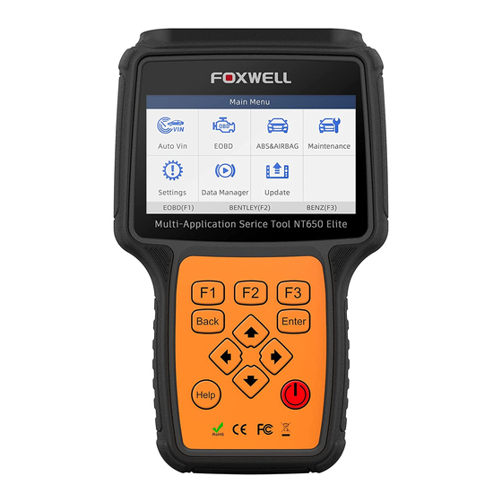
2.1 Scanner Descriptions This section illustrates external features, ports and connectors of the scanner. Figure 2-1 Front View 1 Diagnostic Port - provides connection between vehicle and the scanner. 2 LCD Display - shows menus, test results and operation tips. 3 Function Keys / Shortcut keys - three keys that correspond with “buttons”... -
Page 9: Getting Started
Working Temperature: 0 to 60 ℃ (32 to 140℉) Storage Temperature: -20 to 70℃ (-4 to 158℉) Power Supply: 8-18V vehicle power and 3.3V USB power Dimensions: (L*W*H): 200*100*38mm Weight: 1.8 Kgs 3 Getting Started This section describes how to provide power to the scanner, provides brief introductions of applications loaded on the scanner and display screen layout and illustrates how to input text and numbers with the scan tool. -
Page 10: Input Dialog Box
Figure 3-1 Sample Home Screen 3.3 Input Dialog Box This section illustrates how to use the scan tool to input letters and numbers, such as VIN number, channel number, test values and DTC number. Typically, you may be required to input letters or numbers when you are doing any of the following operations. -
Page 11: Vehicle Identification
Figure 3-3 Sample Numeric Keyboard Screen 3. To delete a letter or number, use the function key Cursor Forward to move the cursor to it and then press the Backspace button. 4. When finished the entry, press Completed key to continue. 4.Vehicle Identification This section illustrates how to use the scanner to identify the specifications of the vehicle under test. - Page 12 Figure 4-1 Sample Main Menu Screen 2. Select Automatic VIN Acquisition from the menu, and press the ENTER key. Figure 4-2 Sample VIN Reading Screen 3. The scan tool starts to communicate with the vehicle and read the Vehicle Specification or VIN Code automatically.
-
Page 13: Manual Vin Entry
Figure 4-4 Sample Manual VIN Entry Screen 5. If it takes too long to get the VIN code, press Cancel to stop and input the VIN manually. Or if failed to identify the VIN, please input the VIN manually or click Cancel to quit. Figure 4-5 Sample Manual Entry Screen 4.1.2 Manual VIN Entry Manual VIN Entry identifies a vehicle by manually inputting a 17-digit VIN code. -
Page 14: Manual Vehicle Selection
Figure 4-7 Sample VIN Reading Screen 3. Press the function key Keyboard and a virtual keyboard opens for VIN entry. Figure 4-8 Sample Manual VIN Entry Screen 5. Input a valid VIN code and use the function key Completed to confirm. The scan tool starts to identify the vehicle. - Page 15 Figure 4-9 Sample Main Menu Screen 2. A screen with vehicle manufacturer areas displays. Select the area where the car brand is originated. A list of vehicle makes display. Figure 4-10 Sample Vehicle Manufacturer Area Selection Screen 3. Select the vehicle manufacturer. A list of vehicle identification options displays. Figure 4-11 Sample Vehicle Selection Screen 4.
-
Page 16: Manual Selection
Figure 4-12 Sample VIN Reading Screen 5. The scan tool starts to communicate with the vehicle and read the Vehicle Specification or VIN Code automatically. Figure 4-13 Sample Automatic VIN Reading Screen 6. Answer YES if the Vehicle Specification or VIN code is correct and a menu of controller selection displays. -
Page 17: Diagnostic Operations
2. On each screen that appears, select the correct option and then press the ENTER key. Do this until the complete vehicle information is entered and the menu of controller selection displays. Figure 4-15 Sample Manual Vehicle Selection Screen 5 Diagnostic Operations This section illustrates how to use the scanner to read and clear diagnostic trouble codes, and view “live”... - Page 18 Figure 5-2 Sample Quick Scan Screen 3. At the end of successful automatic controller scan, a menu with a list of installed controllers together with their DTC overview displays. Figure 5-3 Sample Quick Scan Screen 4. If there is diagnostic trouble code(s) detected in a control unit, press the function key corresponding with Report on the screen to view details of code information.
-
Page 19: Control Modules
Figure 5-5 Function Menu screen 5.1.2 Control Modules Control Modules screen displays all controllers available on the vehicles. The controllers listed on the menu do not mean that they are installed on the vehicle. To select a system for testing: 1. -
Page 20: Diagnostic Operations
5.2 Diagnostic Operations After a system is selected and the scanner establishes communication with the vehicle, the Function Menu displays. The menu options may include: ECU information ● Read Codes ● Clear Codes ● Live Data ● Special Functions ● NOTE Not all function options listed above are applicable to all vehicles. - Page 21 Present/Permanent/Current Codes ● Pending Codes ● History Codes ● Present/Permanent/Current codes stored in a control module are used to help identify the cause of a trouble or troubles with a vehicle. These codes have occurred a specific number of times and indicate a problem that requires repair.
-
Page 22: Clear Codes
Figure 5-12 Freeze Data screen Freeze Frame Data: a snapshot of critical vehicle operating conditions automatically recorded by the on-board computer at the time of the DTC set. It is a good function to help determine what caused the fault. 4. -
Page 23: Live Data
Figure 5-14 Sample Clear Codes Screen 3. Check the codes again. If any codes remain, repeat the Clear Codes steps. 5.2.4 Live Data Live Data menu lets you view and record real time PID data from a selected vehicle electronic control module. - Page 24 Figure 5-16 Sample Live Data Menu Screen 3. Scroll with the up and down arrow keys to highlight a line, and left and right arrow keys to scroll back and forth through different screens of data. Press function key Pause to suspend collecting data from the vehicle and use the Start key to resume collecting data.
-
Page 25: Custom Data List
Figure 5-19 Sample Two PID Graph Screen 6. Press the function key Merge Graph to display two PID plots in one coordinate to check how they affect each other. Figure 5-20 Sample Merge Graph Screen 7. Press the Back key to return to the previous menu. 5.2.4.2 Custom Data List Custom List menu lets you to minimize the number of PIDs on the data list and focus on any suspicious or symptom-specific data parameters. -
Page 26: Special Functions
2. The custom data selection screen displays. Scroll with the up and down arrow keys to highlight a line, press the ENTER key and then repeat the action to make more selections. To deselect an item, select it again and then press the ENTER key. Alternatively, use the function keys Select All and Deselect to select or deselect all items at once. - Page 27 IMPORTANT Before bleeding the brake system, make sure no diagnostic codes are present. Do not let the master cylinder run dry during the brake bleeding procedure. After bleeding the brake system, check the brake pedal for excessive travel or a “spongy” feel. Bleed again if either condition is present.
-
Page 28: Maintenance
Figure 5-24 Sample Function Menu Screen 2. A group selection screen, test selection screen, several step-by-step instruction screens, or bi- directional control screen may appear. Read the screens and follow all instructions. If necessary, use the function keys to perform commands or answer any questions. If more than 3 function keys displays, use up and down arrow keys to select a command and press the ENTER key to confirm. -
Page 29: Oil Service Reset
Figure 6-1 Sample Main Menu Screen 2. Select a service to test and press ENTER key to start. Figure 6-2 Sample Maintenance Screen 6.1 Oil Service Reset Oil Light Reset menu allows you to reset the service lamps on the instrument cluster. The Service Indicator System is designed to alert the driver when the vehicle is due for a service. -
Page 30: Battery Replacement (Brt)
brake pads, and setting brakes after disc or pad replacement, on multiple brands of vehicles where electronic brake systems are fitted. Some tests display a command to the operator. For example, if “Pressing Brake Pedal” displays, the operator has to press and hold the brake pedal and then continue. Actual tests vary by vehicle manufacturer, year, make. -
Page 31: Diesel Particulate Filter (Dpf) Regeneration
Perform BRT on Audi/VW/Seat/Skoda cars - after communicating with vehicles, there’s two ● options under Replace battery menu - Validate battery and Display data. - Validate battery menu lets you to recode the new battery to the vehicle’s ECU and to turn off dashboard warning lights. -
Page 32: Obdii/Eobd Operations
7 OBDII/EOBD Operations OBDII/EOBD menu lets you access all OBD service modes. According to ISO 9141-2, ISO 14230-4, and SAE J1850 standards, the OBD application is divided into several sub programs, called ‘Service $xx’. Below is a list of OBD diagnostic services: Service $01 - request current powertrain diagnostic data ●... -
Page 33: Change Units
1. Scroll with the arrow keys to highlight Language from Settings menu and press ENTER key. Figure 8-1 Sample Settings Screen 2. Press left and right arrow key select a language and press the ENTER key to confirm. Press the Back key to exit and return. -
Page 34: Configure Shortcut Keys
Figure 8-4 Sample Unit Selection Screen 8.3 Configure Shortcut Keys Selecting Shortcuts option lets you to change the functionality of the shortcut buttons. To assign a function to a shortcut button: 1. Scroll with the arrow keys to highlight Shortcuts from Settings menu and press the ENTER key. A screen with available shortcut keys displays. -
Page 35: Configure Beeper
Figure 8-7 Sample Shortcuts Screen 8.4 Configure Beeper Selecting Beep Set opens a dialog box that allows you to turn on/off the beeper. To turn on/off the beeper: 1. Scroll with the arrow keys to highlight Beep Set from Settings menu and press ENTER key. Figure 8-8 Sample Settings Screen 2. -
Page 36: Keypad Test
To test the display: 1. Scroll with the arrow keys to highlight Display Test from Settings menu and press the ENTER key to start test. Check if there are any missing spots in the LCD screen. Figure 8-10 Sample LCD Test Screen 2. -
Page 37: Tool Information
Figure 8-12 Sample Keypad Test Screen 3. To quit the test, press Back key twice. 8.7 Tool Information Selecting About option opens a screen that shows information about your scan tool, such as serial number, which may be required for product registration. To view information of your scan tool: 1.
Need help?
Do you have a question about the NT650 Elite and is the answer not in the manual?
Questions and answers
How to clear the P252F Over Full Oil fault code on a Mitsubishi 2019 Triton Diesel
To clear the P252F Over Full Oil fault code using the Foxwell NT650 Elite on a 2019 Mitsubishi Triton Diesel, follow these steps:
1. Connect the Foxwell NT650 Elite scanner to the vehicle’s OBDII port.
2. Turn on the ignition and power up the scanner.
3. From the main menu, select “OBDII/EOBD”.
4. The scanner will automatically detect the communication protocol.
5. After connection is established, a menu displays. Select “Read Codes” to confirm the presence of the P252F code.
6. After confirmation, select “Clear Codes” from the menu.
7. Follow on-screen instructions to erase the fault code.
Note: Ensure the oil level issue is corrected before clearing the code.
This answer is automatically generated