
Related Manuals for Würth IVT Latento System Controller


Summary of Contents for Würth IVT Latento System Controller
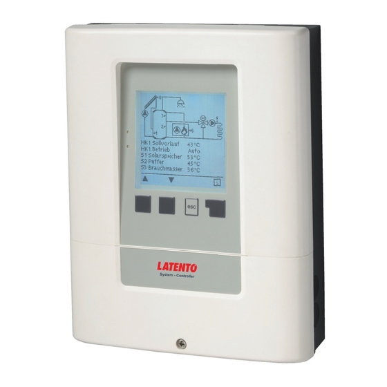
- Page 1 System Controller Installation and operating instructions Read carefully before installation, commissioning and operation...
-
Page 2: Table Of Contents
Content A. - Safety instructions 6.2. - Frost protection 7.3.12. - Boiler pump A.1. - EC declaration of conformity 6.3. - Antilegionella 7.3.12.1. - Boiler pump A.2. - General instructions 6.3.1. - AL T set 7.3.12.2. - BP Tmin A.3. - Explanation of symbols 6.3.2. -
Page 3: A.1. - Ec Declaration Of Conformity
Safety instructions A.1. - EC declaration of conformity By affi xing the CE mark to the unit the manufacturer declares that the Latento System Controller conforms to the relevant safety regulations EC low voltage directive 2006/95/EC as well as the EC directive for electromagnetic compatibility 2004/108/EC. Conformity has been verifi... -
Page 4: A.5. - Warranty And Liability
Safety instructions A.5. - Warranty and liability The controller has been manufactured and tested with regard to high quality and safety requirements. The unit is subject to the statutory guarantee period of two years from the date of sale. The warranty and liability shall not include, however, any injury to persons or material damage that is attributable to one or more of the following causes: Failure to observe these installation and operating instructions Improper installation, commissioning, maintenance and operation... -
Page 5: B.1. - Specifi Cations
Description of controller B.1. - Specifi cations Electrical specifi cations: Mains voltage 100 - 240VAC Mains frequency 50...60Hz Power consumption 0.5 - 3 W Switched power Entire switched power for electronic relays R1 - R2: 460VA for AC1 / 240W for AC3 Electronic relay R1 min.5W...max.120W for AC3 Electronic relay R2... -
Page 6: C.1. - Wall Installation
Installation C.1. - Wall installation 1. Unscrew cover screw completely. Install the controller only in dry areas and under 2. Remove Terminal connection cover. Unscrew the 2 small screws left and right and the ambient conditions remove the upper part of the controller by lifting it out of the socket. Caution described under B.1 “Specifi... - Page 7 Installation C.2.1. Socket 169.3 R4.5 Terminal connection cover Cover screw...
-
Page 8: C.3. - Installing The Temperature Sensors
Installation 1. Select necessary program/hydraulics (s. „Hydraulic vari- C.2.2. ants / Systems / Diagrams“ on page 12) 2. Remove terminal connection cover (s. „C.2.1. Socket“ on page 7) 3. Strip cables by 55mmmax., insert, fi t the strain relief de- vices, strip the last 8-9mm of the wires (Fig. -
Page 9: D. - Terminal Connection
Installation D. - Terminal connection D.1. - Terminal connection The mains part of the terminal connection room is covered by a plastic sheet. Make sure that the controller is without voltage before removing it. VFS2 VFS1 RC21 Bridge Bridge D.2. - Terminal connection diagram Low Voltage PF- relay Relays... -
Page 10: D.3. - Hydraulic Variants / Systems / Diagrams
Installation D.3. - Hydraulic variants / Systems / Diagrams System System 1 System 2 System 3 System 4 System 5 System 6 system 7 Anschluss IVT MV A 1 HK IVT MV A 2 HK IVT MV B 1 HK IVT MV C 1 HK IVT MV E 1 HK IVT MV F... - Page 11 System 8 System 9 System 10 System 11 F 1 HK IVT MV F 2 HK IVT MV G 1 HK IVT 2HK+1WEZ+Solar IVT 2HK+1WEZ Solar (bottom) Storage Solar (bot- Storage Solar (bot- Storage Solar (bottom) tom) tom) HC (middle) Storage HC (middle) Storage HC (middle) Storage HC (middle)
- Page 12 Installation Hydraulic variants / Systems / Diagrams variant System 12 System 13 System 14 System 15 System 16 System 17 System 18 Combi. storage + Hea- Combi. storage+ Com- Combi. storage+ Solar+ Combination store+ 2 Boiler+ Compressor+ Boiler+ Sola Boiler+ Heating circ. connection ting circ.
- Page 13 System 19 System 20 System 21 System 22 System 23 System 24 ar+ Burner Puffer+ Boiler+ Heating Puffer+ Boiler+ Com- Puffer+ Boiler+ Solar+ 2 mixed Heating circ. 2 mixed Heating circ.+ 2 mixed Heating circ.+ circ. pressor Burner Compressor Solar+ Compressor ar (bottom) Storage Solar (bottom) Storage Solar (bottom)
-
Page 14: D.4. - Rc 21 Room Thermostat
Installation D.4. - RC 21 Room thermostat and remote adjuster RC21 is an optional accessory and not included in the scope of supply by default. The Latento System Controller is fully operational without the RC21. Caution The remote adjuster with integrated thermostat RC21 provides you with easy to use temperature controlled adjust- ment of heating from within your living space. -
Page 15: E.1. - Display And Input
Operation E.1. - Display and input The display (1), with its extensive text and graphics mode, is almost self-explanato- ry, allowing easy operation of the controller. To change from the overview to the settings menu, press the „esc“ key. The green status LED (2) lights up when a relay is active, the red LED blinks when an error occurs. -
Page 16: E.2. - Commissioning Help
Operation E.2. - Commissioning help The fi rst time the controller is switched on and after the language and time have been set, a query appears as to whether you want to parametrise the controller using the commissioning help or not. The commissioning help can also be termi- nated or called up again at any time in the special functions menu. -
Page 17: E.4 Menu Sequence And Menu Structure
Operation Menu sequence and menu structure The graphics or overview mode appears when no key has been pressed for 2 minutes, or when the main menu is exited by pressing “esc“. The up and down buttons are used to scroll through the list of sensors and relays You can enter the Main menu by pressing the „esc“... -
Page 18: Measurement Values
Measurement values 1. - Measurement values The menu “1. Measurement values” serves to display the currently measured temperatures. The menu is closed by pressing “esc” or selecting “Exit measurement values”. If “Error” appears on the display instead of the measurement value, then there may be a defective or incorrect temperature sensor. -
Page 19: Days
Statistics 2. - Statistics The menu “2. Statistics” is used for function control and long-term monitoring of the system. The menu is closed by pressing “esc” or selecting “Exit statistics”. For analysis of the system data it is essential for the time to be set accurately on the controller. Please note that the clock continues to run for 24 hours if the mains voltage is interrupted, and must be reset afterwards. -
Page 20: Heating Circuit Day
Periods 3. - Periods Menu “3. Times” is used to set the time, date, operating times for e.g. the heating circuit and hot water. The associated temperature reference values are specifi ed in menu 5 “Set- tings”! Caution The menu is closed by pressing “esc” or selecting “Exit periods”. 3.1. -
Page 21: Cooling Periods
Periods 3.6. - Cooling periods Cooling activity times Set the desired time periods when the cooling (see „7.3.6. - Cooling“ on page 38) should be active. 3 periods can be set per day, settings can also be copied to other days. Outside the set times the cooling function is switched off. Setting range: from 00:00 to 23:59 /default setting: 06:00 to 22:00 3.7. -
Page 22: Operating Modes
Operating Modes 4. - Operating Modes In menu 4. “Operating modes” the controller can either be placed in automatic mode, switched off, or placed in a manual operating mode The menu is closed by pressing “esc” or selecting “Exit operating modes”. 4.1. -
Page 23: Heat Transfer
Settings 5. - Settings The necessary basic settings required for the control function are made in menu “5. Settings”. This does not under any circumstances replace the safety devices to be provided by the customer! Caution The menu is closed by pressing “esc” or selecting “Exit settings”. The following pages contain generally valid descriptions for the settings. -
Page 24: Day Correction
Settings 5.6.3. - Curve The characteristic curve is used to control the heat dissipation of the heating circuit relative to the outdoor tempera- ture. The demand for heat is different due to differences in the type of building/insulation/type of heating/outdoor tem- perature. -
Page 25: Minimum Flow
Settings 5.6.7. - Minimum Flow The minimum fl ow temperature is the lower limit of the heating curve, and by this, the reference fl ow temperature of the heating circuit. Furthermore, this valule is the reference fl ow temperature for the frost protection (see also „6.2. - Frost protection“... -
Page 26: Dhw Reference
Settings 5.8.2. - DHW reference Minimum DHW temperature during operating hours If the set temperature is undershot and the DHW heating charge is enabled i.e. the current time period is set, the DHW additional heating is switched on. Settings range: 10 °C to 60°C / Default: 55°C The request only works when an additional heat source is set as additional function, and the heat source is also set as heat request source (see also... -
Page 27: Error Messages
Settings 5.20. - Error messages Settings for additional function, see also „7.3.20. - Messages“ on page 49 5.21. - Pressure control Settings for additional function, see also „7.3.20. - Pressure monitor“ on page 50 5.22. - Parallel operation R1 Settings for additional function, see also „7.3.22. - Parallel operation R1“ on page 50 5.23. -
Page 28: Protective Functions
Protective functions 6. - Protective functions Menu “6. Protective functions” can be used to activate and set various protective functions. The menu is closed by pressing “esc” or selecting “Exit settings”. This does not under any circumstances replace the safety devices to be provided by the customer! Caution 6.1. -
Page 29: Al Residence Time
Protective functions Antilegionella function is not shown in the menu “Protective functions”. It is instead shown as submenu of the corresponding special function. Special functions with AL are: Solid fuel boiler (s. „7.3.7. - Solid fuel boiler“ on page 39), Solar (s. „7.3.8. - Solar“... -
Page 30: Protective Functions For Solar
Protective functions 6.4. - Protective functions for Solar Antilegionella function is not shown in the menu “Protective functions”. It is instead shown as submenu of the corresponding special function (see „7.3.8. - Solar“ on page 40). Caution 6.5. - System protection Highest Priority Protection System protection prevents overheating of system components by automatic shutdown of the solar pump. -
Page 31: Frost Protection
Protective functions 6.6.2. - Frost protection A two-stage frost protection function can be activated. In stage 1 the controller switches the pump on for 1 minute every hour if the collector temperature drops below the set value “Frost stage 1”. If the collector temperature drops further to the set value “Frost stage 2”... -
Page 32: Special Functions
Special functions 7. - Special functions Menu “7. Special functions” is used to set basic items and expanded functions. Except for the time all settings should only be made by a specialist. Caution The menu is closed by pressing “esc” or selecting “Exit special functions”. The enumeration of the menus may vary from system to system. -
Page 33: Type Of Pump
Special functions Speed control 7.2.2. - Type of pump The type of speed controlled pump must be entered here. Standard: Speed control for standard pumps. 0-10V: Speed control of e.g. High effi cency pumps by 0-10V signal. PWM: Speed control of e.g. High effi cency pumps by PWM signal. The selection of the type of pump is not applicable for R1 and R2. -
Page 34: Relay Functions
Special functions 7.3. - Relay functions Free, i.e. in the specifi c hydraulic variant unused relays, can be assigned to various additional functions. Every addi- tional function can only be assigned once. R1 and R2: ELRs / electronically speed controlled relays. R3 to R6: Mechanical relay 230V R7: Potential free relay V1 and V2: PWM and 0-10 V output... -
Page 35: Heat Transfer
Special functions 7.3.2. - Heat transfer This is used to transfer energy from one storage to another with a pump. Settings range: S1-S8, VFS1-2, Active storage/ Default setting: none 7.3.2.1. - ∆ T Heat transfer Temperature difference for heat transfer function. When the temperature difference between HT Source and HT Drain reaches ∆T Heat Transfer On, the relay is switched on. -
Page 36: Th Set
Special functions 7.3.4. - Thermostat Thermostat is used for time and temperature controlled additional heating. Settings range: On, Off Temperature values which are set too high can lead to scalding or damage to the system. Scalding pro- tection must be provided by the customer! Danger! In Energy savings mode, different settings may apply, see e.g. -
Page 37: Heating Rod
Special functions 7.3.5. - Heating rod Electrical heating rod for the storage Temperature values which are set too high can lead to scalding or damage to the system. Scalding pro- tection must be provided by the customer! Danger! 7.3.5.1. - Heating rod Settings range: On, Off 7.3.5.2. -
Page 38: Co Tref
Special functions 7.3.6. - Cooling This is used to cool e.g. storages down to a reference temperature by radiating heat or for a time- and tem- perature controlled air conditioning. 7.3.6.1. - Cooling Settings range: AC, simple, Off 7.3.6.2. - Co Tref The reference temperature at thermostat sensor 1. -
Page 39: Solid Fuel Boiler
Special functions 7.3.7. - Solid fuel boiler The relay is used to control the pump of an additional solid fuel boiler. 7.3.7.1. - Solid fuel boiler Settings range: On, Off 7.3.7.2. - SF Tmax Maximum temperature in the storage. If this is exceeded, the relay is switched off. Settings range: Off to 100°C / Default setting: 85°... -
Page 40: Tmin S (X)
Special functions 7.3.8. - Solar This function is used to control a solar pump. 7.3.8.1. - Solar Settings range: On, Off 7.3.8.2. - Tmin S (X) Enable/start temperature at sensor X: If this value is exceeded at the applicable sensor X and the other conditions are also met, then the controller switches on the associated pump and/or valve. -
Page 41: Solar Bypass
Special functions 7.3.9. - Solar bypass Use the relay to switch a bypass valve or a bypass pump This can direct the fl ow past the storage, when the fl ow temperature at the bypass sensor is lower than the storage that has to be charged. -
Page 42: Dhw Request
Special functions 7.3.11. - Burner This function activates a heat request for a burner, as soon as Tref is undershot, until Tref + hysteresis is reached, or a request from the heating circuit or the domestic hot water is present. In Eco Mode, energy saving settings are used when the solar pump is running. -
Page 43: Boiler Pump
Special functions 7.3.12. - Boiler pump The boiler pump is switched with the burner. This menu is only available when the additional function burner is active. 7.3.12.1. - Boiler pump Settings range: On / Off 7.3.12.2. - BP Tmin Minimum temperature at the burner sensor to enable the boiler pump. As soon as this temperature is exceeded at the set sensor, and suffi... -
Page 44: Dhw Request
Special functions 7.3.13. - Compressor This is used to switch a relay to control a compressor of a heat pump. 7.3.13.1. - Compressor Settings range: On, Off 7.3.13.2. - DHW request The compressor is started for a domestic hot water request. Settings range: On, Off 7.3.13.3. -
Page 45: Heating Circuit 2
Special functions 7.3.16. - Heating circuit 2 A heating circuit pump is switched on and off depending on the reference value. The reference temperature is calculated by a combination of outdoor temperature and characteristic curve. 7.3.16.1. - Heating circuit 2 Settings range: Off, Auto, Continous Day, Continous night, Reference Value, 14 day reference 7.3.16.2. -
Page 46: Day Correction
Special functions The diagram shows the infl uence of the selected characteristic curve steepness (standard curve) on the calculated reference fl ow temperature of the heating circuit. The correct curve is appointed by setting the intersection point of the calculated maximum fl ow tem- perature and the minimum outdoor temperature. -
Page 47: Minimum Flow
Special functions 7.3.16.9. - Minimum Flow The minimum fl ow temperature is the lower limit of the heating curve, and by this, the reference fl ow tempera- ture of the heating circuit. Furthermore, this valule is the reference fl ow temperature for the frost protection (see also „6.2. -
Page 48: Return Fl Ow Increase
Special functions 7.3.17. - Return fl ow increase This function is used to raise the temperature of e.g. the return fl ow by making it pass through the storage. Settings range: On, Off 7.3.17.1. - Return fl ow increase Settings range: On, Off 7.3.17.2. -
Page 49: Circulation Tmin
Special functions 7.3.19. - Circulation A ciculation pump at the domestic hot water storage is temperature and time controlled by this function. 7.3.19.1. - Circulation Settings range: On, Off 7.3.20.1. - Circulation Tmin If the temperature drops below this value during a circulation period at the circulation sensor, or a heat request is caused due to water being tapped, the circulation pump is started. -
Page 50: Pressure Monitor
Special functions 7.3.21. - Pressure monitor The relay is switched on when the pressure drops below set minimum or exceeds the set maximum pressure. Settings range: On, Off / Default setting: Off 7.3.21.1. - Pressure monitor This menu is used to confi gure the system pressure montoring via direct sensor. As soon as the set limits are exceeded, the relay is switched on. -
Page 51: Heat Quantity
Special functions 7.3.25. - Heat quantity Constant fl ow When the heat metering mode „Flow rate“ is selected, an approximated heat quantity is calculated using the values the user has to enter. These are type of glycol/AntiFreeze, glycol portion and fl ow rate. These values are put into correla- tion with the temperature data of collector sensor and storage sensor. -
Page 52: Pressure Monitor
Special functions 7.3.26. - Pressure monitor A message is shown when the pressure drops below set minimum or exceeds the set maximum pressure. No relay is switched, for that see „7.3.21. - Pressure monitor“ on page 50. 7.3.27. - Pressure monitor A message is shown and the LED fl... -
Page 53: Free Storage
Special functions 7.7. - SD-Card Settings for the data logging and fi rmware update function with SD card. 7.7.1. - Logging Activate the logging function and set the fi le format used. Settings range: CSV, TSV, JSON, Off / Default setting: Off 7.7.2. -
Page 54: Menu Lock
Menu lock, Service values, Languages 8. - Menu lock Menu „8. - Menu lock“ can be used to secure the controller against unintentional changing of the set values. The menu is closed by pressing “esc” or selecting “Exit menu lock”. The menus listed below remain completely accessible despite the menu lock being activated, and can be used to make ad- justments if necessary: Measurement values... -
Page 55: Z.1. Malfunctions With Error Messages
Malfunctions Z.1. Malfunctions with error messages If the controller detects a malfunction, the red light fl ashes and the warning symbol also appears in the display. If the error is no longer present, the warning symbol changes to an info symbol and the red light no longer fl ashes. Led blinks + warning symbol) To obtain more detailed information on the error, press the key underneath the warning or info symbol. -
Page 56: Z.2 Replacing The Fuse
Malfunctions and Maintenance Replacing the fuse Repairs and maintenance may only be performed by a specialist. Before working on the unit, switch off the power supply and secure it against being switched on again unintentionally! Check for the absence of power! Danger Only use the supplied spare fuses or fuses of the same design with the following specifi... -
Page 57: K.1.1. - Output Signal
Manual pump confi guration K. - Appendix Manual pump confi guration (see „7.2. - Speed control“ on page 32). It is recommended however to use the preset profi les. K.1. - Pump In this menu, preconfi gured profi les for various pumps can be selected. Please note that individual settings are still possible even when a profi... - Page 58 Manual pump confi guration K.1.10. Example for pump settings Speed Max rpm Min rpm 0-5% Cable break detection Stop 5-20% Stop 25% Start Start 25-90% Area of control PWM-Signal (%) 20% 25% 100% PWM on >=25% PWM max <= 90% PWM off 5% - 20% K.1.11.
-
Page 59: Useful Notes / Tips And Tricks
Useful notes/tips and tricks Instead of setting the fl ow rate for the system using a fl ow rate limiter, it is better to adjust the fl ow rate using the switch on the pump and by means of the “max. speed” setting on the controller (see „7.2. - Speed control“). This saves electric energy. - Page 60 Hydraulic variant set: Commissioned on: Commissioned by: Your specialist dealer: IVT GmbH & Co. KG Gewerbering Nord 5 D - 91189 Rohr Hotline: +49 9876 9786 97 Fax +49 9876 9786 98 info@ivt-rohr.de • www.ivt-rohr.de Atomthreads LWIP: Portions of the regulator fi rmware are Copyright (c) 2010, Kelvin Lawson. All rights reserved. Portions of the regulator fi...
Need help?
Do you have a question about the IVT Latento System Controller and is the answer not in the manual?
Questions and answers