Table of Contents
Advertisement
Quick Links
Advertisement
Table of Contents

Subscribe to Our Youtube Channel
Related Manuals for Biamp Cambridge Qt 300


Summary of Contents for Biamp Cambridge Qt 300
- Page 1 Qt® 300/600 Installation and Operations Guide...
-
Page 5: Table Of Contents
Table of Contents Safety Information Qt 300/600 Introduction Sound Masking Emitter Types Hardware Installation Installing the Control Module Wall Mount Rack Mount Installing the Qt Emitters Standard Emitter Installation Active Emitter Installation Table 1 Installing Paging or Music to the Audio Inputs Installing Contact Closures Custom Cabling Guidelines Important Considerations... - Page 6 MCS: Administration Section Service Zone Names Networking and Security Notification of Errors Date and Time – Time Zone Setting Equalizers and Emitter Fault Detection Equalizer Update Emitter Network Fault Detection MCS: Help Links to Help Topics Operations and Administration Software Update MCS: Printout Error Codes and Clear Error Post-Installation Handoff...
-
Page 7: Safety Information
Safety Information Read these instructions Keep these instructions Heed all warnings. Follow all instructions. Do not use this apparatus near water. Indoor use only. Clean only with dry cloth. Do not block any ventilation openings. Install in accordance with the manufacturer’s instructions. Do not install near any heat sources such as radiators, heat registers, stoves, or other apparatus (including amplifiers) that produce heat. -
Page 8: Qt 300/600 Introduction
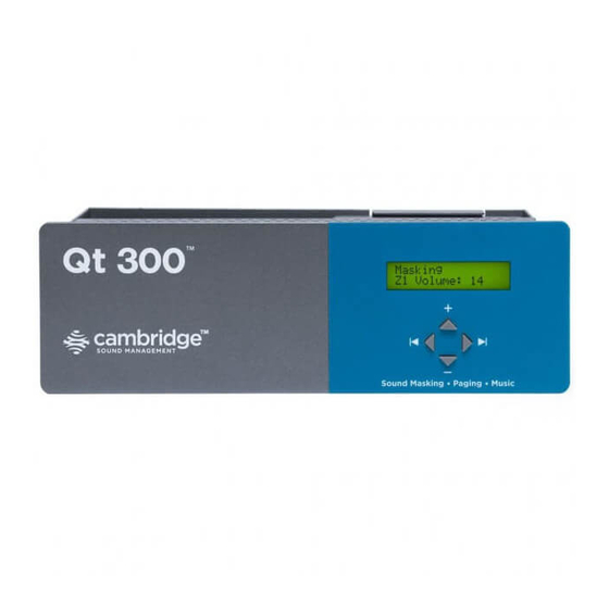
Qt 300/600 Introduction This manual discusses the installation of a sound masking system using either the Qt 300 or the Qt 600. The Qt 300 and Qt 600 controllers have identical functionality, but different number of zones supported - the Qt 300 supports 3 zones whereas the Qt 600 supports 6 zones. - Page 9 Setting the masking volumes can be approached in one of two ways: BEST: If a sound level meter is available, it is recommended that the control module’s masking volumes be adjusted up or down to achieve the following readings on the meter: •...
-
Page 10: Hardware Installation
Hardware Installation Installing the Control Module NOTE: Always plug/unplug power supply at wall outlet. NOTE: The Qt 600 is shown in the figures, but the Qt 300 installs in the same manner. Wall Mount Mount the bracket using the three screws and plastic anchors (mollies) provided. Use a 1/4 inch drill bit for the anchor hole. -
Page 11: Installing The Qt Emitters
Step 1 Remove the QtPro and power supply bracket from wall mount bracket Step 2 Reassemble power supply to right rack mount bracket using 6-32 black screws (included with bracket). Step 3 Fasten left and right rack mount brackets to QtPro using the screws removed in Step 1 Step 4 Mount QtPro to 19”... -
Page 12: Active Emitter Installation
Gather all ceiling tiles (per layout drawing) that are to receive emitters. Use the supplied hole saw to cut holes in designated tiles. Cut all tiles from the front. (Different types of emitter housings are available to attach in areas where there are no suspended ceiling tiles.) Push the emitter through the front of the hole in tile and secure it by pushing down and twisting the locking ring at the back of the emitter. -
Page 13: Installing Paging Or Music To The Audio Inputs
Table 1 Zone Type Ceiling Height Vol Level Intended Result (at listener ear level) Open Office Areas < 9’ (2.75m) 11-14 45-48 dBA Open Office Areas 9’-10’ (2.75-3m) 12-15 45-48 dBA Open Office Areas 10’-11’ (3.0-3.3m) 13-16 45-48 dBA Open Office Areas 11’-12’... -
Page 14: Custom Cabling Guidelines
Custom Cabling Guidelines Important Considerations Use solid conductor 24 AWG CAT-3 cable that meets local code requirements. If the system is installed in a return air plenum, the cable must be plenum rated. Shielding is not required. Unshielded twisted pair (UTP) cable is acceptable. Snagless boots are not required RJ-45 plugs must use the “bent 3-tine”... -
Page 15: System Configuration
Use a ball-point pen to dislodge the existing battery. Insert a new battery with the positive (+) side facing upward. Replace the connection panel, securing all six screws. Reconnect the zone run cables System Configuration After the QtPro is mounted, the power can be turned on and settings modified to test wiring to the connected emitters. -
Page 16: Configuring The Control Module For The Network
Configuring the Control Module for the Network IP Address DHCP The IP address is preset for systems that are not on the network. To directly connect to the control module over Ethernet, use any internet browser and placee the IP address or control module name in the navigation bar. If the MCS is not used, DHCP will allocate an IP address when the system is connected to the network. -
Page 17: Setting Sound Masking Levels
Shown in the next block is the display for the IP Address. This is a default value that can be used in a browser, for direct connection. As noted, DHCP will change it when the system is on a network. IP AddressDHCP 169.254.1.1 The Host Name is set at the factory to a default value. -
Page 18: Setting Audio Input Levels
If installation occurs before the office is occupied, turn the system to the desired level and leave it at that level. If the system is installed after the office is occupied, turn the system to the correct level when the space is unoccupied and employ auto ramping, only supported through the MCS, to provide for a period of acclimatization To set the masking level for a zone, use the arrow keys on the front panel to move to the right until the zone... -
Page 19: Lock/Unlock The Front Panel
Lock/Unlock the Front Panel The settings of the Qt 600/Qt 300 can be locked by a physical switch on the back of the control module. Lock the control module panel by moving the lock switch to the LOCKED position. This prevents any casual interaction from changing the settings. -
Page 20: Reset System To Default Settings
Reset System to Default Settings To clear an error indication (after problem is fixed) or reset the settings to the initial default state, the system should go through a hard reboot Steps for the hard reboot: Unplug the power and wait 15 seconds or more. Hold the up arrow on the front panel and re-connect power. -
Page 21: Dhcp Support
Connecting to the Qt 300/600 over Ethernet System software is operated from any network browser. Software is pre-installed in the control module. The HELP function provides comprehensive software control operating instructions. Connect a computer or the network to the 10/100 Ethernet jack. Power the control module on by plugging it into a standard wall outlet. -
Page 22: Setting Emitter Type And Masking Spectrum Per Zone
Operations Section in Modify Mode: The Operations Section contains three blocks. The block on the left allows zone selection and shows the emitter configuration for each zone. The Apply to Zones block in the middle allows the configuration of the following: NOTE: It is not possible to select an AE spectrum with a standard Qt emitter. -
Page 23: Changing Masking Level Using Mcs
Changing Masking Level Using MCS Follow these steps to update the parameters within the masking level block: Review – selecting the REVIEW button will allow the user to select a zone and see the current configuration. Click on the zone on the left side of the Operations Section. To modify a zone, start by clicking the MODIFY button. -
Page 24: Changing Inputs A And B Min/Max Levels
After Auto Ramp is enabled, the masking level will be set to the Start Auto Ramp level. The first ramp will start on the Auto Ramp Start Date until the 2nd Auto Ramp Date is reached which will set the masking level to the 2nd Auto Ramp Level. -
Page 25: Time Of Day Masking And Audio
Select NORMAL SIGNAL to use the signal as it comes to the controller and adjust volume from the zone window. Use LOW SIGNAL to add 12 dB to the signal or HIGH SIGNAL to subtract 12dB from the signal and then continue the adjustment of volume in the zone window. -
Page 26: Errors
Errors If the QTPro control module is operating properly, software will display Status: OK on right side of the Operations Section. If the control module encounters an error, software will display Status: Error (with additional data) on right side of the Operations Section. Click on the Error link on the Operations Section to obtain additional information. -
Page 27: Mcs: Administration Section
MCS: Administration Section The following section will use this screen for reference: IMPORTANT: Only update one block at a time and only press the related Submit button before moving on! Changes to blocks that are not submitted will be lost if a different block is submitted. Service The Service block holds the following fields: •... -
Page 28: Networking And Security
Networking and Security Use this block to obtain the control module’s MAC and IP Addresses, to change its NETBIOS Host Name, and to change the Username or Password for logging in. If you change the control module’s Host Name, QtPro will automatically advertise its new NETBIOS name. -
Page 29: Setting Equalizers And Emitter Fault Detection
If the RTC is to be used, it should be set prior to adjusting operating levels. The RTC is set using the pull-down menus under “Administration: Date and Time”. You MUST set the day-of-the-week (e.g. Sun, Mon, Tues, etc.), the date, and the time. The RTC will only be used if the control module has been unable to access an external time server since it was powered on. -
Page 30: Emitter Network Fault Detection
Operations Section with the equalizer block displayed after a higher level password has been entered: Emitter Network Fault Detection The ENFD is a feature used after installation to monitor the status of the emitter cable runs. As shown on the screen, the installation should be complete without defect before the ENFD feature is enabled. -
Page 31: Mcs: Help
After the 15 minutes are expired and the system is fully installed, it is time to enable fault detection, if you desire. It is not required for proper operation. The window shown below shows that after the 15 minutes have expired there is a drop-down menu in the upper right corner that allows 3 actions: Refresh settings - this is used just before enabling ENFD to make sure any setup data is cleared and proper measurements will be taken. -
Page 32: Links To Help Topics
Links to Help Topics From the Help screen on the MCS, there are links to some common questions when using the MCS. The main link to the Help document is shown on the right under the caption for support. Operations and Administration This information is also contained within this document. -
Page 33: Error Codes And Clear Error
Error Codes and Clear Error System errors are shown on the control module front panel display. If an error occurs, the message “Status: Error” will be displayed on the control panel. To determine the cause of the error, press NEXT (right arrow button), to display the error code. -
Page 34: Post-Installation Handoff
is the same as shown on the front panel. The Error result pop-up below shows there are emitter faults in 3 zones and the administrator should look for nonfunctional emitters. Click OK to close the Error result pop-up window. Click the acknowledge link and the Status displayed goes back to OK. If the actual error persists, the Status will eventually change to report the same error again. -
Page 35: Warranty
Warranty Note: This equipment has been tested and found to comply with the limits for a Class A digital device, pursuant to part 15 of the FCC Rules. These limits are designed to provide reasonable protection against harmful interference when the equipment is operated in a commercial environment. This equipment generates, uses, and can radiate radio frequency energy and, if not installed and used in accordance with the instruction manual, may cause harmful interference to radio communications. - Page 36 Obtaining warranty repairs: Please access and review online help resources for the product before requesting warranty service. If the product is still not functioning properly after making use of these resources, please contact Cambridge Sound Management for a return authorization number. All returns are to be prepaid. The warrantor will pay return surface freight within the continental United States on warranty repairs.
- Page 38 800.218.8199 Dynasound is either a trademark or registered trademark of Biamp Systems, LLC in the United States and other countries. Other product names referenced may be trademarks or registered marks of their respective owners and Biamp Systems is not affiliated with or sponsored by these companies. All specifications are subject to change.
Need help?
Do you have a question about the Cambridge Qt 300 and is the answer not in the manual?
Questions and answers