Table of Contents
Advertisement
Quick Links
Advertisement
Table of Contents

Summary of Contents for THOR3D Calibry
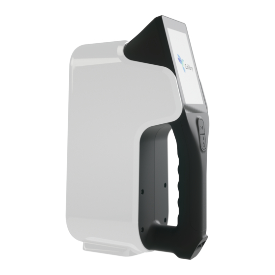
- Page 1 3D scanner User manual...
- Page 3 This guide provides information on how to install and use Calibry software, how to operate the scanner, and recommendations for the scanning process itself. When using the device, keep in mind that the 3D scanner is a high-precision optical device that requires careful attention.
-
Page 4: Front Panel
User manual Scanner hardware device Front panel Geometric camera Texture camera Texture flash Projector... - Page 5 3D scanner Scanner hardware device Rear panel Touch screen Button «START» Button «STOP» Scanner data cable connector...
-
Page 6: Pre-Starting Procedure
User manual Pre-starting procedure Connect the scanner to a computer with the Calibry Nest software installed. • Strictly follow the connection sequence. Make all connections when the power supply unit is disconnected. Connect the power supply unit when all other connections have been made. Otherwise, the equipment may be damaged, and this case will not be covered under the warranty. -
Page 7: Main Screen Elements
3D scanner Scanner operation Main screen elements After the scanner is loaded, the main screen is displayed Status bar The status bar shows the status of the scanner Control panel The control panel is used to display the sidebar. Here you can also specify the name of the current project (the object being scanned) by clicking on... - Page 8 User manual Scanner operation List of scans The sidebar presents information on the available and occupied space on the hard disk of the computer, to which the scanner is connected, as well as buttons for scanner settings and the scanner data.
- Page 9 3D scanner Scanner operation List of scans The list of scans During the scanning pro- cess, the list of all scans carried out will be placed on the main screen. The scans are sorted by crea- tion date: the newer, the higher.
- Page 10 User manual Scanner operation List of scans Any scan in the project can be deleted by simply swiping the item in the list sideways. You can cancel the deletion within 5 seconds by clicking the «Cancel» button. You can delete all scans by clicking the «Delete All Scans»...
-
Page 11: Preview Mode
3D scanner Scanner operation Preview Mode The preview mode allows you to select the correct scan angle, to determine the optimal distance, to assess the nature of the surface, to set up the scan pa- rameters, and to determine the adequacy of the number of markers applied. To enter the mode, press the button, on the main screen of the scanner. - Page 12 User manual Scanner operation Preview Mode Screen frames rate This parameter determines the frame update rates on the scanner screen during preview and scan modes. Increase the setting value to improve the picture quality displayed on the scanner screen. If increasing the value slows down the scanning, decrease it back.
- Page 13 3D scanner Scanner operation Preview Mode Texture brightness This parameter determines the frame texture brightness. If you change the value of this parameter, the image from the texture cam- era is displayed on the scanner screen, so you can visually assess the texture quality in advance.
- Page 14 User manual Scanner operation Preview Mode Projector capacity Set this parameter to one of the following values. To select the maximum, average or minimum projector capacity, respec- tively. As a rule, the maximum capacity mode is used to scan dark objects. The minimum capacity mode is recommended for scanning shiny objects.
-
Page 15: Scan Mode
3D scanner Scanner operation Scan mode To start the scan session in the preview mode, press the button at the bottom of the screen. For convenience, you can also use the mechanical button located under the screen. To finish the scan session, click the button at the bottom of the screen. - Page 16 User manual Scanner operation Scanning in geometry tracking mode Use the geometry tracking mode when capturing objects with distinct geometry and without many flat parts. Scan rate (frames per second) Number of frames shot During scanning, it is important to keep the optimal distance between the scanner and the object being scanned.
- Page 17 3D scanner Scanner operation Scanning in marker tracking mode Scan in marker tracking mode if the object does not have characteristic fea- tures of geometry or texture, as well as if these features make up a periodical- ly repeating pattern. Number of markers in the frame When scanning by markers, it is important...
- Page 18 User manual Scanner operation Scanning in texture tracking mode Scan in texture tracking mode if the object has characteristic texture features, while scanning in geometry or marker tracking mode is not possible. Far border of the scanner working area Near border of the scanner working area Near border...
- Page 19 Calibration of the scanner The Calibry scanner is an accurate measuring tool that is factory calibrated. In order to ensure high scanning accuracy, Calibry has the option of custom calibration. A simple test is sufficient to detect if the scanner needs to be calibrated. In geometry tracking mode, try to «look»...
- Page 20 User manual Scanner operation Calibration of the scanner To prepare for calibration, assemble the calibration stand. For easy assembly, it is recommended to screw the top panel of the stand to the scanner in advance. Place the scanner about 50 cm away from the calibration stand.
- Page 21 3D scanner Scanner operation Calibration of the scanner Everything is ready for calibration. To start the calibration procedure, turn on the scanner and go to the side panel. • Select «Scanner» and «Calibration» • Click «START» The device will start scanning, and the message will appear on the screen asking you to move the scanner to the first position.
- Page 22 User manual Scanner operation Calibration of the scanner The scanner needs to be aligned in three As soon as the desired position is found, the directions: scanner will display the message «Freeze», and the red circles will become blue. Do not 1.
-
Page 23: Scanner Operation
3D scanner Scanner operation Calibration of the scanner Slowly move the scanner away from the Once the scanner is calibrated in all seven calibration board. The indicator on the left positions, you will be prompted to restart the scanner software and the device will be side of the screen lets you know how much the scanner should be moved. -
Page 25: Software Manual
3D scanner Software manual... - Page 26 The software (SW) includes several modules. Calibry Tray Manager. This module is designed to provide the scanning pro- cess and to acquire raw data. Calibry Nest. This module is designed for raw data postprocessing and sav- ing of the obtained 3D model in a conventional format.
-
Page 27: System Requirements
If there is more than one graphics card in your computer (e.g., both In- tel and NVIDIA) make sure that Calibry software always uses the more high-performance graphics card by default. We do not recommend that you use screens with 4K resolution. - Page 28 Microsoft web site and installing it yourself: https://www.microsoft.com/en-us/download/details.aspx?id=48145 On successful startup, the Calibry Nest window will open, and in the notifi- cation area in the right-bottom corner the Calibry Tray Manager icon will appear.
- Page 29 Each Calibry scanner is supplied with a calibration file containing its individ- ual settings. If necessary, a calibration file can be requested from distributor. To interact with the scanner its calibration file should be loaded to Calibry Nest. If you plan to connect several scanners to one computer then calibra- tion files should be loaded for each one of them.
- Page 30 • Startup with System – automatic module startup when the computer is booted up. About – module version. The Scanner window is provided for the scanner to work in Calibry Nest. Scanner control buttons are located at the top of the window: • Exit from preview/scanning mode;...
- Page 31 3D scanner The scan list is located under the control button. To begin working with a scan, double-click the respective line, and raw data will be opened for postprocessing. Right-click the scan list to activate the pop-up menu: • Open folder – click to select a folder where scans will be saved; •...
- Page 32 Software manual Calibry SW – Postprocessing Raw Data Raw data from scanning represents a set of frames captured by the scanner and used for 3D model building. Most of the frames are geometrical. Each geometric frame contains a certain number of points on the surface of the object being scanned.
- Page 33 3D scanner Apart from frames, raw data contain several files with additional information. The data set described above is written into a file with .ascan extension, also called a project file. Opening a Project File To begin working with a project you should open it using one of the following methods: 1.
- Page 34 Software manual Data Visualization A visualization window is used to view scanned data and the results of its pro- cessing. When working with data, a user can view: • A cloud of points formed by one frame. Select the required geometric frame in the project tree;...
- Page 35 3D scanner Simple Postprocessing Simple postprocessing is the name for data postprocessing when only one pro- ject file is used for 3D model creation. This means that to obtain the model only one scanning session was launched, i.e., the entire object has been scanned once as a whole.
- Page 36 Software manual After registration At the registration stage, a preliminary cleaning procedure can be executed by specifying the corresponding setting. This procedure will automatically re- move those points from the cloud that will be determined by the algorithm as noise or other data not relevant to the object being scanned. After preliminary cleaning...
- Page 37 3D scanner Finalization At the finalization stage, the cloud of points is converted into a polygonal model. In this case, it is necessary to specify certain algorithm settings. In the top of the window you can select an array of preset settings de- pending on the scanner model and the scanned object.
- Page 38 Software manual The result of running the algorithm with a low resolution (4 mm) The result of running the algorithm with a high resolution (0.7 mm)
- Page 39 3D scanner Fill holes. On the obtained surface of the 3D model, holes can appear. If the real object being scanned actually has holes on its surface, this is normal. But sometimes the holes are formed as a result of insufficient raw data. In this case the situation can be corrected algorithmically at the finalization stage.
- Page 40 Software manual Sharpness. This parameter determines the appearance of the polygon mesh. At a low level of sharpness, the polygons are merged more smoothly, without sharp angles, while high sharpness makes geometry more detailed and thus the image becomes more clear.
- Page 41 This parameter can vary depending on the model of your scanner, as well as on marker type: markers can be both magnetic and printed by you on the printer. Markers are not removed on the texture Calibry DRAKE Maxi DRAKE Midi DRAKE Mini...
- Page 42 Cut height is counted from the floor and is specified according to how the model has been scanned. When the Thor3D rotary table is used the parameter of 150 mm should be set, when scanning is executed without this table the value of 5 mm should be set.
- Page 43 Texture mapping Calibry scanners are equipped with a color camera which allows you to take images of three-dimensional surfaces with texture. Texturizing is performed by projecting separate captured color frames onto a finished 3D model. The Texture size can be specified manually by choosing one of three provided op- tions: 1024 ×...
- Page 44 2.5. Simplification [Percent of initial model / Number of triangles in new model] Texture mapping [Texture size] When any postprocessing procedures are executed, the Calibry SW can- not execute other operations. Scanning, opening and processing other projects, etc. are impossible. Wait for completion of the current post- processing procedure in order to proceed with new operations.
- Page 45 3D scanner Multiple Postprocessing To build 3D models of certain objects, it is sometimes necessary to execute several scanning sessions. Most frequently, this is necessary to scan an object from all directions. E.g., scanning an object from above and then turning it over and to scan from below.
- Page 46 Software manual Automatic alignment For simplicity, at first let’s consider the procedure of automatic alignment an object of three parts by markers. In the project window, highlight the 3D models of all components to be aligned and click Alignment by points. The alignment window will appear. The working alignment window is divided into three parts: 1.
- Page 47 3D scanner Eventually, the resulting model consisting of parts #1 and #2 will be displayed in the basic window, just like in the result window. We need to «stick» the remaining third part to this model. To do this, left-click it in the scan list window (Meshes for alignment).
- Page 48 Software manual Click Add Aligned to Base once more. The other parts of the object can be added to the base model in a similar way until all of them «stick» to the base. When all parts are aligned together click Accept Changes. The complete point cloud of an aligned model will be displayed on the screen.
- Page 49 3D scanner Everything is ready for starting up multiple registration and multiple finaliza- tion procedures. The intent of these procedures, as well as settings applied are similar to the relevant procedures for simple postprocessing. The difference is only in that for their execution the data obtained in several scanning sessions is used together.
- Page 50 Software manual To place an alignment point, double-left-click it first on the base and then on the second model. Specify a minimum of three alignment points. Double-click a point to remove it. Press and hold CTRL key and move a point to relocate it.
- Page 51 3D scanner In the context of our example, let’s begin to highlight frames starting from the very first. Having added more than 4000 frames to selection we see that divergencies in leg geometry are still not present. Now let’s begin to review frames from bottom to top starting from the last. From a certain moment (approximately from Frame #4050) the leg starts to split.
- Page 52 Software manual Deleting Bad Frames In the context of the relevant example, it can be noted that the 3D model is obtained even without the last group of frames which cause the splitting of the leg. Therefore, all the frames starting from #4051 onward can simply be deleted.
- Page 53 3D scanner In the context of the relevant example, you can try not to delete frames ##4051–4455 as bad frames, but simply “erase” the leg image on them by deleting the corresponding points from the cloud. 3D Model Processing Left-click the 3D model resulting from postprocessing. To the right of the pro- jects, the toolbar will be displayed.
- Page 54 Software manual Cut on Frames. When the button is pressed all selected areas of model sur- face are deleted not only from the model itself but also from corresponding frames. Fill selected holes. When the button is pressed the list of all holes detected by the algorithm on the 3D model surface is displayed in the project tree.
- Page 55 3D scanner...
- Page 56 Software manual Texture correction. When this tool is selected this window appears: Adjust brightness, contrast and color balance using the relevant sliders or numeric field settings. Click OK to save your settings. Luminosity brush. This is a tool for textured model processing. Move the cursor over the model surface to increase texture brightness.
- Page 57 3D scanner Other Calibry SW Capabilities Ruler Enables you to measure the distance in millimeters between two selected points in frames or on a model. Interface The interface tab enables editing of user interface settings and includes the following settings: •...
- Page 59 DRAKE User manual...
-
Page 60: Scanner Operation
Drake. User manual Scanner operation To begin To turn the scanner on, press the power button which is located under the screen. Wait until the scanner loads and the main window appears on the screen. The main window will contain: •... - Page 61 DRAKE Scanner operation Control Panel Here, you can change the name of your scan by pressing the heading in the center. All objects scanned will be placed in the folder with that name. If the folder is not named, by default it will be named like “SCAN_ 20170101”...
- Page 62 Drake. User manual Scanner operation List of Scans List of scans The center of the screen is devoted to the list of scans. These scans are sorted by date (the newest on top) and are located in the appropriate folder. There is an icon next to each scan, which represents the first frame captured.
- Page 63 DRAKE Scanner operation After pressing this button, your files will begin to copy, with the exception of those that are already on the USB drive. To delete any unnecessary scan from the hard-drive, simply swipe your finger across the scan. You can cancel any deletion within 5 seconds by pressing Cancel.
- Page 64 Drake. User manual Scanner operation Preview Mode Turn on Preview Mode by pressing this button. To stop scanning press. Begin every scan in the Preview Mode. This timal distance is shown in green, so try to keep allows you to find the right distance to the the scanner at that distance to the object dur- object, evaluate the surface, and gauge wheth- ing scanning.
-
Page 65: Marker Mode
DRAKE Scanner operation Marker Mode To activate or deactivate «Marker» Mode toggle on/off the switch during Pre- viewing: While scanning with markers, it is important that each frame contains at least 3 markers. Because markers are identified in real-time by the software at up to 12 times per second, not every marker will get identified in every frame. - Page 66 Drake. User manual Scanner operation Frequency of Texture Frames This parameter indicates with what fre- quency the recording of texture frames is carried out. These frames are needed for texturizing the final model. The lower the parameter, the higher the frequency and thereby the higher the amount of texture frames recorded.
- Page 67 DRAKE Scanner operation Flash Indicator There are three modes for the power of the circular LED flash. Circular LED flash capacity Full flash Half flash Flash light turned off Color mode This feature allows you to capture black and shiny objects. If the object is black use –...
- Page 68 Make it higher or lower to make the texture more or less bright. This proves especially useful for scanning humans as this setting helps achieve the most natural-looking texture. You also might like to leave the default value, and instead adjust brightness when processing the model in Calibry Nest software.
- Page 69 DRAKE Scanner operation Wi-Fi Settings To enable wireless data transfer from Drake to a network computer via a local Wi-Fi connection, first plug in a USB Wi-Fi adapter. An indicator will appear in the top right corner of the screen (an antenna with a line through it). This indicates that the Wi-Fi adapter is plugged in, but not yet connected to the local network.
- Page 70 Calibration of the scanner Manual calibration The Drake 3D scanner is a precise measurement instrument and is factory- calibrated. In order to ensure high accuracy of every scan, Thor3D has a calibration procedure that the user can perform himself. Preparation for calibration To calibrate the scanner, unpack the calibration stand and assemble it.
- Page 71 DRAKE Scanner operation Calibration of the scanner Calibration procedure To begin calibration procedure, turn on the scanner and open Side Panel. • Select “Scanner” and “Calibration” • Press “Start” The device will start to scan and the screen will prompt you to move into the first position.
- Page 72 Drake. User manual Scanner operation Calibration of the scanner Once the positioning is correct, the scanner will prompt you to Freeze and the red indicator circles will turn green. Do not move the scanner while this is happening. It will take 2-3 seconds to finish. Once finished, the screen will prompt for second position.
- Page 73 DRAKE Scanner operation Calibration of the scanner * To ensure the highest accuracy, do not calibrate the scanner in a well lit room (avoid direct sunlight) and in high or low temperatures. The scanner is best calibrated in a room with temperatures between 21 and 24 degrees C (70 and 75 degrees F).
- Page 74 Drake. User manual...
Need help?
Do you have a question about the Calibry and is the answer not in the manual?
Questions and answers