
Related Manuals for Muller Elektronik Joystick III

Summary of Contents for Muller Elektronik Joystick III
- Page 1 Installation and operating instructions Joystick III Version: V2.20141208 3032258305-02-EN Read and follow these operating instructions. Keep these operating instructions in a safe place for later reference.
- Page 2 Company details Document Installation and operating instructions Product: Joystick III Document number: 3032258305-02-EN From software version: 7.03 Original language: German Copyright © Müller-Elektronik GmbH & Co.KG Franz-Kleine-Straße 18 33154 Salzkotten Germany Phone: ++49 (0) 5258 / 9834 - 0 Fax: ++49 (0) 5258 / 9834 - 90 Email: info@mueller-elektronik.de...
-
Page 3: Table Of Contents
Table of contents Table of contents Product description Assembly instructions Fitting a joystick with a D-Sub connector Fitting a joystick with a CPC connector Configuring the joystick Operation Executing functions Changing the brightness of the LED Assigning functions Viewing functions Technical specifications Technical specifications of the joystick D-Sub connector pin allocation... -
Page 4: Product Description
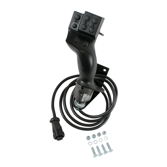
Product description Product description Joystick III Eight buttons Numbering of the buttons Side-mounted switch Manufacturer's plate [➙ 12] The joystick is an ancillary operating device which can rapidly access the functions of an ISOBUS job computer. The joystick is fitted with eight buttons and a single side-mounted switch, which enables switching between three levels. -
Page 5: Assembly Instructions
Assembly instructions Fitting a joystick with a D-Sub connector Assembly instructions The joystick is available in two versions: ▪ With D-Sub connector (item no.: 3032258305) – Variant for vehicles with additionally installed ISOBUS basic equipment from Müller-Elektronik. ▪ With CPC connector (item no.: 3032258606) –... -
Page 6: Fitting A Joystick With A Cpc Connector
Assembly instructions Fitting a joystick with a CPC connector Fitting a joystick with a CPC connector Mounting angle Connector for connection to the vehicle's ISOBUS in-cab- For attachment in the cabin connector Procedure You fit the joystick as follows: 1. Fit the joystick next to the driver on the right. ⇨... -
Page 7: Configuring The Joystick
Configuring the joystick Configuring the joystick Brightness for day or night mode: Selected auxiliary protocol Day mode Selected joystick number Cursor Function Meaning icon Switches between day and night mode Increase brightness Reduce brightness When configuring the joystick, you can make the following settings: ▪... - Page 8 Configuring the joystick If you don't know which protocol your system supports, you can test this by selecting protocol "AUX2". If you can then assign functions [➙ 9] for the ISOBUS job computer to the joystick, your system supports Auxiliary 2. Otherwise, select protocol "AUX1".
-
Page 9: Operation
Operation Executing functions Operation Executing functions Each button on the joystick can be assigned three functions. The position of the side-mounted switch determines the function which is performed when the button is pressed: Position of the switch Color of the LED Yellow Green Procedure... - Page 10 Operation Viewing functions You have selected the appropriate protocol when configuring the joystick. [➙ 7] Your ISOBUS job computer is connected to the vehicle's ISOBUS in-cab- connector. You have assigned functions to the joystick. [➙ 9] 1. Start the terminal. 2.
-
Page 11: Technical Specifications
Technical specifications Technical specifications of the joystick Technical specifications Technical specifications of the joystick Parameter Value Operating voltage 10.5V to 16V DC Temperature range -20°C to +70°C Power consumption 40mA Protection rating IP20 D-Sub connector pin allocation Pin no. Signal Pin no. -
Page 12: Disposal
Technical specifications Disposal Disposal When it has reached the end of its service life, please dispose of this product as electronic scrap in accordance with all applicable waste management laws. Information on the nameplate The nameplate is located on the underside of the joystick. Possible abbreviations on the rating plate Abbreviation Meaning... -
Page 13: Notes
Notes Notes V2.20141208...
Need help?
Do you have a question about the Joystick III and is the answer not in the manual?
Questions and answers