Table of Contents
Advertisement
Advertisement
Table of Contents

Related Manuals for GBF PL960 Series


Summary of Contents for GBF PL960 Series
- Page 1 G B F WiFi IP Doorbell USER MANUAL 41100101...
- Page 2 IP Doorbell system in minutes. You may connect the PL960 Series of IP Doorbells to your LAN (Local Area Network) either through a Wireless (WiFi) connection or a Wired (Ethernet Cable) connection.
-
Page 3: Table Of Contents
CONTENTS Package Contents ………………………………..…………………………. 4 Device Illustrations .…………………………………... …………………………. 5 1.0 Installation ……………………………………………………………………… 6 Installation Wiring Diagrams …………………….. ….…………………….. 7 2.0 Configuration Preparations ………....………………………… 10 3.0 Network Configuration ......………………………….12 3.1.1 Configuration Using the Android App ....12 3.1.2 Configuration Using the iOS App ....... 13 3.2 Adding a configured or wired IP Doorbell .... - Page 4 4.2.3 Motion Detection ………………………………………….. 17 4.2.4 Set Time ............17 4.2.5 Reboot/Restore ..........18 4.3 Deleting a device from the App ........18 4.4 ControlCam2 Doorbell Connection Operation .... 18 4.4.1 Answering a Call ..........18 4.4.2 Unlocking the Door ........... 19 4.4.3 Monitoring the Outdoor Station …………………….
- Page 5 5.3 Set Unlock Duration Time ………………………………………… 23 5.4 Add User Access Codes ……………………………………………. 24 5.5 Delete User Access Codes ……………………………………….. 24 5.6 Delete User Access Codes Directly …………………………… 24 5.7 Setting the Length of the Access Codes and Programming Password ……………………………………………………………….. 24 5.8 Delete All Settings (Maintains Programming Password)26 5.9 Factory Default (Keypad Settings only) …………………….
-
Page 6: Package Contents
PACKAGE CONTENTS (1) GBF PL960M/QPM/TPM IP Doorbell (1) Metal Back Box (1) External Wi-Fi Antenna with 3’ Cable (1) 12VDC Power Supply (1) Relay/Push-to-Exit Wiring Harness (1) Bell Connector Wire Set (1) Varistor (blue case, see wiring diagrams) (4) Screws with Anchors... -
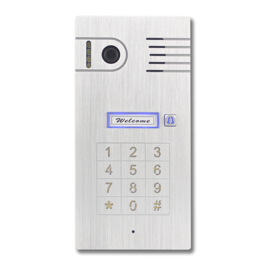
Page 7: Device Illustrations
- 5 -... -
Page 8: Installation
1. Installation *NOTE: It may be more convenient to perform the initial configuration of the IP Doorbell with it temporarily connected to power nearby your home internet router and a computer. This way testing and operation can be verified before the unit is mounted permanently. -
Page 9: Installation Wiring Diagrams
Back case Screws Rain Cover - 7 -... - Page 10 ____________________________________________ - 8 -...
- Page 11 _______________________________________________ __________________________________________ - 9 -...
-
Page 12: Configuration Preparations
2. Configuration Preparations Begin by performing a factory reset of the settings in your IP Doorbell. To default the settings to factory, follow these steps; 1. Connect the WiFi antenna with outdoor station or connect your Router directly to the IP Doorbell with an ethernet cable attached to the RJ45 connector. - Page 13 IP Doorbell. 1. Make sure your smartphone is connected to the WiFi network to which you want the GBF IP Doorbell to be connected. 2. Open the app. 3. Create an account by clicking on the ‘Sign up’ button.
-
Page 14: Network Configuration
3. Network Configuration 3.1.1. Configuration Using the Android App 1. Inside the app, click on the button or on the ‘Click here to add device’ icon. 2. Choose the “Doorbell2” option, then choose the ‘Hotspot Connection’ option. 3. Click ‘Next’ to start searching automatically for your new device’s configuration SSID. -
Page 15: Configuration Using The Ios App
3.1.2 Configuration using the iOS App 1. Inside the app from the “Doorbell” screen, click on the button or on the ‘Click here to add device’ icon. 2. Choose the “Doorbell2” option, then choose the ‘Hotspot Connection’ option. 3. Press on ‘Next’. 4. -
Page 16: Adding A Configured Or Wired Ip Doorbell
3.2 Adding a configured or wired IP Doorbell You can add a previously configured or wired IP Doorbell device using three methods: LAN search, QR code scan, and manual entry. 1. Connect your mobile device to the Wi-Fi/LAN network which contains the IP Doorbell. -
Page 17: Manually
3.2.3 Manually 4. Press the ‘Manual Input’ button. 5. Manually insert the device's GID, referencing the GID label placed on the back cover of the device. In the device’s details screen, insert the default password ‘1234’. You may change the device’s name to any desired name (no spaces or special characters, maximum 20 characters), and press ‘Save’. -
Page 18: Unlock Time
4.1.2 Unlock Time The unlock time duration is hard-keyed in to the IP Doorbell during installation using the 2-position switch on the back of the IP Doorbell. Any unlock duration time entered here will no longer affect the duration of the unlock relay activation. 4.1.3 One-Key Unlock To activate the IP Doorbell’s unlock relay from the app without the necessity to enter the ‘unlock password’, you can optionally activate the... -
Page 19: Modify Unlock Password
4.2.2 Modify Unlock Password A password is required to activate the IP Doorbell’s unlock relay from the app. This step is also required to allow the ‘One-Key Unlock’ function. 1. In the ‘Advanced Settings screen’ click on ‘Modify Unlock Password’. 2. -
Page 20: Reboot/Restore
4.2.5 Reboot/Restore In case of a minor malfunction of your device, you can try to correct the issue using this option. Use Reboot to force a reset on the device, and Restore to force a factory reset. *NOTE: Performing a ‘Restore’ erases settings stored during the configuration process. -
Page 21: Unlocking The Door
4.4.1 Answering a call (cont) You can 'Accept’ or 'Decline’ a call from the pop-up call alert of the app. If accepting, you will see ‘Live’ video and would need to use the following steps to have a conversation with the visitor; 1. -
Page 22: Video Record
4.4.5 Video record During a call or monitoring mode, click on the icon to start recording a video of the outdoor station’s image. Click again to finish the recording. It can be accessed from the 'Main Menu' screen, in ‘Media’. 4.4.6 Silencing Audible Doorbell Notifications 1. -
Page 23: Accessing Recorded Videos/Images
4.4.9 Accessing recorded videos/images 1. From the 'Doorbell’ or ‘Ring Mode’ screen, click on the main menu icon to access the ‘Main Menu’ screen. 2. Select the ‘Media’ option. 3. The first tab shows the recent files (images and videos), the second shows only videos and the third only images. -
Page 24: User Account Configuration
4.5. User Account Configuration Access the user account’s settings by clicking on the main menu icon from the ‘Doorbell’ or ‘Ring Mode’ screen’, then click on your profile image or your username, accessing the ‘Account’ screen. 4.5.1 Change User Account Password 1. -
Page 25: Keypad Programming
5. Keypad Programming (PL960QPM/TPM) The PL960QPM/TPM keypad can be custom programmed with up to 40 different access codes, and will trigger the same relay that is triggered through the ControlCam2 App. The length of the access codes and programming password can be programmed to be two to six digits in length (globally). -
Page 26: Add User Access Codes
5.4 Add User Access Codes: 1. Enter programming mode. 2. Enter two digits (01 – 40) representing the slot in which the user code will reside, a longer beep is heard. 3. Enter the new user code (length determined through other programming);... -
Page 27: Delete All Settings (Maintains Programming Password)26
3. Within 3 seconds, press the ' ’ button. A longer beep is heard, indicating the keypad programming has been restored to factory default settings. GBF Electronics Inc 110A-12811 Clark Place Richmond, BC Canada, V6H 2H9 Tel: 604-278-6896 or 604-285-8721 Fax: 604-278-6895 info@gbfelectronics.com... -
Page 28: Troubleshooting
Troubleshooting: During Hotspot Configuration, when the App is searching for a device to be added I get a 'No new device found. Please check the device status, and you need to allow app getting location info permission and stop VPN service' error message: Check the antenna connection to your IP Doorbell and make sure that it is located within range of your mobile device and your router. - Page 29 Troubleshooting (cont.) When I try to connect to the live video of my IP Doorbell, I get a message saying ‘Connecting’ or ‘Connected’, but I do not get any video: This is usually caused by poor communication through the internet between your IP Doorbell and your mobile device.
- Page 30 Troubleshooting (cont.) The video I see from my IP Doorbell is soft and slightly washed out; Please ensure that the protective film adhering to the camera lens is removed after installation. If I try to delete an IP Doorbell from my ControlCam2 App I get an error message stating 'delete fail': Many settings in the ControlCam2 App are stored on our cloud- based servers, and require an internet connection for changes to be made.
-
Page 31: Appendix A: Installation Tips
WiFi range. With these in mind, here are some recommendations; Antenna Placement - One of the advantages of the GBF IP Doorbell is the fact it has an external high-gain antenna (instead of the small wire antennas designed to fit within a plastic chassis). -
Page 32: Weatherproofing
Weatherproofing The GBF 960 Series carry an IP55 (Ingress Protection) rating, meaning that it is sufficiently protected from damage by dust, water, and human contact. This also means that your IP Doorbell is protected from low pressure jets of water (e.g. wind driven rain), but it is not sufficiently protected against a high pressure water stream (e.g. -
Page 33: Wiring
Wiring Wire Connectors: As there is limited room within the IP Doorbell casing for wires, it is suggested to use gel-filled “B” Connector wire splices (blue-beans). Not only are these connectors thin, the dielectric gel inside them prevents your connections from experiencing corrosion issues, and they can be crimped with standard pliers! Poor Man’s POE: If the length of a hardwired cable run is not excessively long, you could also use the 'poor man's POE' by removing (or cutting) the unused blue and... -
Page 34: Appendix B: Disabling The Ip Doorbell Ssid Broadcast
Appendix B: Disabling the IP Doorbell SSID Broadcast When an IP Doorbell is successfully configured using WiFi, the device ‘Hotspot’ is automatically disabled. However, IP Doorbells that are hardwired to your router for internet access will still have the ‘Hotspot’ mode enabled and will be broadcasting an SSID (although without the external antenna attached, the range of this SSID broadcast will be very limited). - Page 35 Appendix B: (cont.) 4. Enter the ‘User Name’ (default is ‘admin’). 5. Enter the ‘Password’ (default is ‘1234’). 6. Click ‘Login’. 7. Click ‘Config’ tab. 8. Expand ‘Network Settings’. 9. Click ‘Wireless’. 10. Depending on the build version of your IP Doorbell, you will either click ‘Close’, or choose ‘WLAN Mode’...
- Page 36 USER MANUAL GBF Electronics Inc Tech Support: 604-278-6896 or 604-285-8721 https://gbfelectronics.com info@gbfelectronics.com...
Need help?
Do you have a question about the PL960 Series and is the answer not in the manual?
Questions and answers