Table of Contents
Advertisement
Quick Links
NEBMM12G8E...S1G15
Encoder cable
Instructions | Assembly
8107328
2019-05b
[8107330]
Translation of the original instructions
1
Applicable documents
All available documents for the product è www.festo.com/pk.
2
Safety
2.1
Safety instructions
–
Do not connect or disconnect plug connector when powered.
–
Only assemble the product on components that are in a condition to be safely
operated.
2.2
Intended use
Connection of motor EMME-AS to motor controller CMMP-AS at connection X2B.
3
Configuration
3.1
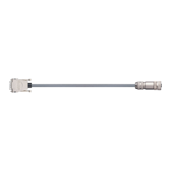
Product design
Fig. 1
Fig. 2
The filter 6 is only required for cable lengths of ³ 10 m.
3.2
Contact assignment
Electrical connec
Pin
Signal
tion 1
Field device side
1
GND
2
Us
3
Data+
4
Data–
5
+SIN
6
REFSIN
7
+COS
8
REFCOS
Tab. 1 Contact assignment
Festo AG & Co. KG
Ruiter Straße 82
73734 Esslingen
Germany
+49 711 347-0
www.festo.com
8107328
1 Socket M12, 8-pin, A-coded (1x)
2 Plug Sub-D, 15-pin (1x)
3 Cable (1x)
4 Screw-type lock
5 Screw (2x)
6 Filter (1x)
CAMF-C5-FC
7 Screw (4x)
Pin
Electrical connec
tion 2
Controller side
3
10
12
5
15
8
14
7
4
Mounting
4.1
Mounting of electrical connection 1
Fig. 3
1. Align socket 1 with the pins of the plug (A).
2. Lay out encoder cable 3 so it is not twisted.
3. Connect socket 1 to the plug (A).
4. Tighten screw-type lock 4. Tightening torque: 0.4 Nm ± 20 %
Ä Screw-type lock 4 is at distance x (approx. 5.6 mm) from the plug con-
nector (B).
Fig. 4
4.2
Mounting of electrical connection 2
With cable lengths < 10 m
1. Align the plug 2 to match the socket.
2. Insert the plug 2 into the socket.
3. Tighten 5 screws. Tightening torque: 0.1 Nm ± 20 %
With cable lengths ³ 10 m
1. Align the plug 2 to match the socket.
2. Insert the plug 2 into the socket.
3. Mount filter 6 between the controller (Anschluss X2B) and the plug 2.
4. Tighten 5 screws. Tightening torque: 0.1 Nm ± 20 %
5. Tighten 7 screws. Tightening torque: 0.1 Nm ± 20 %
4.3
Mounting in energy chain
1. Lay the chain out lengthwise.
2. Place the cables in the chain, making sure they are not twisted.
3. Separate cables from each other using separators/drill holes.
4. Do not connect cables together.
Fig. 5
5. Maintain space X. X > 10 % of the cable diameter D.
If the chain is suspended vertically: increase the space X.
Fig. 6
6. Align chain in the operating position:
–
Make sure that the radius is greater than the bending radius R of the
cables.
–
Cables can move freely in the bending radius KR of the energy chain.
Ä Cables are not forced through the chain.
7. Mount the energy chain è corresponding instructions.
8. Fasten cables:
–
At both ends of the chain in case of short energy chains
–
Only at the driver end in the case of long, sliding energy chains
Advertisement
Table of Contents

Related Manuals for Festo NEBM-M12G8-E S1G15 Series


Summary of Contents for Festo NEBM-M12G8-E S1G15 Series
- Page 1 4. Tighten screw-type lock 4. Tightening torque: 0.4 Nm ± 20 % Ä Screw-type lock 4 is at distance x (approx. 5.6 mm) from the plug con- nector (B). Translation of the original instructions Applicable documents All available documents for the product è www.festo.com/pk. Fig. 4 Safety Mounting of electrical connection 2 With cable lengths < 10 m Safety instructions 1.
- Page 2 Fig. 7 9. Do not bend cables all the way to the fastening point. Ä Mounting space A between the fastening point and bending movement is observed. NOTICE! Damage to cables if the chain breaks. • Replace cables after a chain break. NOTICE! Malfunction and material damage due to vertically suspended cables.
Need help?
Do you have a question about the NEBM-M12G8-E S1G15 Series and is the answer not in the manual?
Questions and answers