
Related Manuals for PeakTech 4025


Summary of Contents for PeakTech 4025
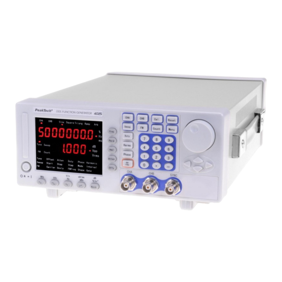
- Page 1 ® PeakTech 4025 / 4030 DDS Function Generator 20 mHz - 5 MHz ® PeakTech 4025 DDS Function Generator 20 mHz - 20 MHz ® PeakTech 4030 Operation Manual...
- Page 2 Safety Precautions This product complies with the requirements of the following European Community Directives: 89/336/EC (Electromagnetic Compatibility) and 73/23/EEC (Low Voltage) as amended by 93/68/EC (CE-marking). To ensure safe operation of the equipment and eliminate the danger of serious injury due to short-circuits (arcing), the following safety precautions must be observed.
- Page 3 Introduction of PeakTech DDS Function Generators ® With Direct Digital Synthesis Technique(DDS), PeakTech DDS function generators are of the high performance indexes and numerous function characteristics which are necessary for the fast completion of measuring. The simple and clear front panel design and the display interface of number and indicator light are convenient for the users to operate and observe.
- Page 4 Frequency measuring:Cymometer can be selected to measure the frequency of external signal. Power amplification: Power amplifier can be selected and the output power can reach to 7W. PeakTech DDS function generators and accessories (package list) PeakTech DDS function generator 3-core power supply Q9 testing cable Q9 bi-nip wire 《...
-
Page 5: Chapter One Brief Introduction
Chapter One Brief Introduction ® The front panel and Rear panel of PeakTech DDS function generators are described in this chapter so as to help users to master the usage as quickly s possible. - Page 6 1.1.2 Plug in and turn on the function generator To guarantee the safe operation of the instrument, the following conditions should be achieved. Voltage:AC 100-240V Frequency:50/60 Hz Power:<30VA Temperature:0~40 Humidity:80% Plug the power connector into power socket outlet on the rear panel with safe earth- wire.
-
Page 7: Screen Description
Rear Panel 1. AC power socket 2. Fan 3. External Modulation Input Terminal 4. Input of frequency measurement 5. Power Amplifier Input 6. Power Amplifier Output 1.3 Screen description There are two rows of digisplay on the screen. The parameters of time such as frequency, period, interval, gate time, frequency deviation modulation, duty cycle and others are shown on the upper row. -
Page 8: Keyboard Description
Table of function option Frequency of Frequency of Exterior Frequency Frequency channel A channel B measuring function sweeping modulation sine sine frequency Exterior Frequency of Frequency of Start Carrier measuring channel A channel B frequency frequency frequency Period of Period of Carrier Gate time channel A... -
Page 9: Basic Operation
The keys of 【 Freq 】 【 Perd 】 【 Ampl 】 【 Atten 】 【 Offs 】 【 Duty 】 【Harmo】【Phase】:To select the options with shadow in the table of function options directly. The key of【pp/rms】:To select the Peak-peak value and Virtual value of the amplitude circularly. - Page 10 In this way, other option data can also be adjusted by the knob ,which will not restated again. Setting of period of channel A :Set the period to be 25ms 【Perd】【2】【5】【ms】 Setting of amplitude of channel A :Set the amplitude to be 3.2V 【Ampl】【3】【.】【2】【V】...
- Page 11 frequency of channel B”. The setting method of frequency, period, amplitude, Vpp, Vrms, waveform, duty cycle of channel B is the same as those of channel A. Setting of harmonic waveform of channel B:Set the frequency of channel B is the once harmonic waveform of channel A.
-
Page 12: Chapter Two Principle Summarize
Phase shift of channel B:0° Start frequency:500Hz End frequency:5kHz Step frequency:10Hz Interval time:10ms Sweeping mode:0 (positive) Carrier frequency:50kHz Carrier amplitude:1Vpp Frequency modulation:1kHz Frequency deviation modulation:5.0% Modulating waveform:sine Gate time:1000ms Chapter Two Principle summarize In the present chapter, users will acquaint with the basic concept of the signal forming and the interior operation of the generator so as to know more about the specifications and use the generator in the best way. - Page 13 2.1 Principle frame Keyboard Displayer Knob Clock Digital circuit Modulation input Lowpass Comparator TTL output Amplitude Output Voltage Power control attenuation amplification amplification and AM 20-60dB Offset setting Output Output A protection Power Output B Amplitude Lowpass amplification control 2.2 Working principle of DDS To generate a voltage signal, the traditional analog signal source adopts electronic components as oscillator in different ways.
-
Page 14: Chapter 3 Handling Instruction
waveform memorizer. DDS uses phase adding technique to control the address of waveform memorizer. Add a phase increment on the present result of phase accumulator in each sampling clock period so as to change the output frequency value by change phase increment. According to the address from the phase accumulator, take the quantized data out from the wave memorizer and then convert it into analog voltage via digit-analog converter and operation amplifier. - Page 15 Frequency modulation(FM) Exterior measurement Parameter calibration 3.1 General operation rule 3.1.1 Data input: If an item is selected, the parameter value can be entered by ten numeric keys writing from left to right. If there are more than one decimal point entered in a parameter, only the first one is valid.
- Page 16 accurate way. The Step entering method can only be used in the frequency of channel A or the amplitude of channel A. 3.1.3 Knob adjusting : In practice, signal needs to be adjusted sequentially sometimes, so number adjusting knob will be used. There is a blink position of cursor in the numeric display.
- Page 17 accurate, the period values of real output signal will be greatly different. The user should know fairly well. 3.2.3 Setting of amplitude of channel A : Press the key of 【 Ampl 】 and the current amplitude will be displayed. Then use the numeric keys or the knob to enter the amplitude value.
- Page 18 continually. But if the amplitude of signal is small in the attenuation of 0dB, the distortion of waveform will be larger and the signal-to-noise ratio is worse. 3.2.6 Output load: The setting value of amplitude is calibrated when the output end is open.
- Page 19 offset value. For the Vpp of amplitude less than 0.2V, the real output offset is one percent of the set offset value. It will be more convenient using the numeric keys than the knob when adjusting DC offset for output signal. In general case, whether DC offset is positive or negative, DC level will rise if turning right and fall if turning left.
- Page 20 3.2.11 Setting of duty cycle of channel A : Press the key of 【 Duty 】 and the channel selects square automatically. The duty cycle is displayed. The value can be entered by the numeric keys or by the knob. The square with set duty cycle will be output.
- Page 21 phase difference is. For example, the resolution of the phase difference is 28.8°when the frequency is 1MHz. Linking the signals of two channels to the oscilloscope, setting the harmonic times and phase difference of the signals of two channels, various stable Lissajous figures can be obtained.
-
Page 22: Frequency Modulation(Fm)
Positive sweeping(0):The frequency of output starts from the start frequency adding by frequency step, restarts to sweep from the start frequency after it gets the end frequency. negative sweeping(1):The frequency of output starts from the end frequency subtracting by frequency step, restarts to sweep from the end frequency after it gets the start frequency. - Page 23 reach to 5MHz only. 3.5.2 Setting of amplitude of carrier waveform Press the key of 【Menu】 to light up the indicator light of “Carrier” and the value of amplitude of carrier waveform will be displayed. The setting of carrier frequency can be set by the numeric keys or adjusting of knob.
- Page 24 that of carrier signal. The amplitude of exterior signal should be adjusted according to the requirements of frequency deviation modulation or depth of amplitude modulation. The larger the amplitude of the exterior modulation signal, the larger the frequency deviation modulation or depth of amplitude modulation. When using exterior modulation, the frequency deviation modulation should be set to be 0 and the interior modulation signal should be closed.
-
Page 25: Parameter Calibration
change. The latter setting is appropriate to measure the time stability of frequency in short time. 3.6.3 Low pass filter: If the measured frequency is lower and high frequency noise is included in the measuring of the external signal, there will be the effect of trigger error resulted from the noise. - Page 26 Calibrating of carrier frequency : In the frequency modulation, carrier 3.7.3 synthesizer uses controllable clock reference. Although the carrier frequency is still the frequency of channel A, it should be calibrated in addition. Pressing the key of 【Menu】 , the indicator lights of “FM” and “Carrier” will be on. The calibrating code of carrier frequency will be displayed on the upper row.
-
Page 27: Frequency Counter
of 7Vrms. Using the voltage meter with real virtual value measures the output AC voltage. Micro-potentiometer RP3 is used to calibrate output voltage to(7±0.02) Vrms. 3.8.2 Calibration of offset of channel A: Set the attenuation of channel A to be 00dB ,... -
Page 28: Chapter 5 Specifications
4.2.1 Input voltage : The multiple of the power amplifier is double and the maximum output amplitude is 22Vpp. So the maximum input amplitude should be limited within 11Vpp. The output signal will be distorted beyond the limitation. 4.2.2 Frequency range: The frequency range of the power amplifier is 10Hz ~ 150kHz. - Page 29 5.1 Output characteristics of channel A 5.1.1 Waveform characteristics: Waveform types:16 types including sine,square,triangle, ramp and so on Waveform length:1024 points Sampling rate:100 MSa/s Amplitude resolution:8 bits Harmonic distortion:≥40dBc(<1MHz),≥35dBc(1MHz~10MHz) ≥30dBc(20MHz~40MHz) Total distortion: ≤1%(20Hz~200kHz) Pulse, square: rise/fall time:≤35ns over pulse:≤ 10 % Duty cycle:...
- Page 30 5.1.5 Sweeping characteristics: linear frequency sweeping Sweeping range:the start/end point can be set arbitrarily Sweeping step: any value greater than the resolution Sweeping rate:10ms~60s/ step Sweeping mode:positive, negative, to-and-fro 5.1.6 Frequency modulation characteristics: Carrier signal: Channel A Modulation signal:interior signal of channel B or exterior signal Frequency deviation modulation:0%~10%...
-
Page 31: General Characteristics
5.3 Output characteristics of TTL 5.3.1 Waveform characteristics: square,rise/fall time≤20nS 5.3.2 Frequency characteristics: same as the output of channel A 5.3.3 Amplitude characteristics: compatibility of TTL,CMOS, low level < 0.3V ,high level > 4V 5.4 General characteristics 5.4.1 Power conditions: voltage:AC220(1±10%)V; frequency:50(1±5%)Hz;... - Page 32 This manual considers the latest technical knowing. Technical changings which are in the interest of progress reserved. We herewith confirm, that the units are calibrated by the factory according to the specifications as per the technical specifications. We recommend to calibrate the unit again, after one year. ® ©PeakTech 03/2008 /Th...
Need help?
Do you have a question about the 4025 and is the answer not in the manual?
Questions and answers