Table of Contents
Advertisement
WARNING
FIRE OR EXPLOSION HAZARD
Failure to follow safety warnings exactly
could result in serious injury, death or
property damage.
mable vapors and liquids in the vicinity of
this or any other appliance.
— WHAT TO DO IF YOU SMELL GAS
•
Do not try to light any appliance.
•
Do not touch any electrical switch; do
f i r e - p a r t s . c o m
not use any phone in your building.
•
Leave the building immediately.
•
Immediately call your gas supplier
from a neighbor's phone. Follow the
gas supplier's instructions.
•
If you cannot reach your gas supplier,
— Installation and service must be per-
agency or the gas supplier.
WARNING: If not installed, operated and maintained
in accordance with the manufacturer's instructions,
this product could expose you to substances in fuel
or from fuel combustion which can cause death or
serious illness.
WARNING
A barrier designed to reduce the risk of burns from the
hot viewing glass is provided with this appliance and shall
be installed for the protection of children and other at-risk
individuals.
INSTALLATION INSTRUCTIONS
INSTALLER: Leave this manual with the appliance.
CONSUMER: Retain this manual for future reference.
HOT GLASS
WILL
CAUSE BURNS.
DO NOT TOUCH
UNTIL COOLED.
NEVER
ALLOW CHILDREN
TO TOUCH GLASS.
BAY WINDOW MANTIS MODELS
-
FIREPLACE MANTIS MODELS
Attention: Check local codes for venting requirements.
This appliance may be installed in
an aftermarket, permanently located,
manufactured home (USA only) or mobile
home, where not prohibited by state or local
codes.
This appliance is only for use with the type
of gas indicated on the rating plate. This
appliance is not convertible for use with other
GLASS
POWER-VENT
HIGH-EFFICIENCY
FIREPLACE WITH
BF28(B,C,G)M(N,P)-5
BI28(B,C,G)M(N,P)-5
BP28(B,C,G)M(N,P)-5
FF28BM(N,P)-3
FI28BM(N,P)-3
FW28BM(N,P)-3
™
Page 1
Advertisement
Table of Contents

Related Manuals for Empire Comfort Systems Mantis Series


Summary of Contents for Empire Comfort Systems Mantis Series
- Page 1 ™ INSTALLATION INSTRUCTIONS INSTALLER: Leave this manual with the appliance. CONSUMER: Retain this manual for future reference. POWER-VENT WARNING HIGH-EFFICIENCY FIRE OR EXPLOSION HAZARD FIREPLACE WITH Failure to follow safety warnings exactly could result in serious injury, death or BAY WINDOW MANTIS MODELS property damage.
-
Page 2: Table Of Contents
TABLE OF CONTENTS SECTION PAGE IMPORTANT SAFETY INFORMATION .................... 3 SAFETY INFORMATION FOR USERS OF LP-GAS ............... 4 REQUIREMENTS FOR MASSACHUSETTS ................... 5 INTRODUCTION ..........................6 SPECIFICATIONS & ACCESSORIES ....................7 INSTALLATION AND GENERAL SAFETY INFORMATION ............. 8 GAS SUPPLY ........................... 9 VENT CLEARANCES ........................ -
Page 3: Important Safety Information
Mantis and have questions, should con- • Any safety screen, guard, or barrier removed for servic- tact Empire Comfort Systems, Inc. prior to installing the ing an appliance must be replaced prior to operating the appliance to avoid creating a hazardous operating condi- appliance. -
Page 4: Safety Information For Users Of Lp-Gas
SAFETY INFORMATION FOR USERS OF LP-GAS LP-GAS WARNING ODOR If a gas leak happens, you should be able to smell the gas because of the odorant put in the LP-Gas. That’s your signal to go into immediate action! that IMMEDIATELY. NO ODOR DETECTED - ODOR FADE f i r e - p a r t s . -
Page 5: Requirements For Massachusetts
REQUIREMENTS FOR MASSACHUSETTS “GAS VENT DIRECTLY BELOW. KEEP CLEAR OF ALL OBSTRUCTIONS”. 1. INSTALLATION OF CARBON MONOXIDE DETECTORS. through 4. f i r e - p a r t s . c o m EQUIPMENT VENTING SYSTEM NOT PROVIDED. APPROVED CARBON MONOXIDE DETECTORS. Each installation instruction. -
Page 6: Introduction
INTRODUCTION Electrical Connections WARNING The safety information listed below must be followed Gas Piping and Gas Pipe Pressure Testing during the installation, service, and operation of this product. Failure to following the safety recommenda- tions could result in possible damage to the equip- General Installations ment, serious personal injury, or death. -
Page 7: Specifications & Accessories
SPECIFICATIONS & ACCESSORIES Fireplace Mantis Models F(F,I,W)28BM(N,P) Bay Window Mantis Models B(F,I,P)28(B,C,G)M(N,P) Height Height ACCESSORIES Common To Bay Window and Fireplace Mantis Part Number Description f i r e - p a r t s . c o m Wall Thermostat - Wireless Remote FRBTP PVCA PVCT... -
Page 8: Installation And General Safety Information
INSTALLATION AND GENERAL SAFETY INFORMATION General Information Note: Any alteration of the original design, installed other than as Note: shown in these instructions will be the responsibility of the person and company making the changes, and will void the warranty. This product may not be used with any type of gas other than what is shown on the rating plate. -
Page 9: Gas Supply
GAS SUPPLY Pressure Testing of the Gas Supply System Note: Other Than All-Metal Construction Recommended Gas Pipe Diameter the unit. In Inches In Inches Nat. L.P. Nat. L.P. Manual Shut-off Valve 0-10 feet 10-40 feet f i r e - p a r t s . c o m 40-100 feet 100-150 feet Leak Testing... -
Page 10: Vent Clearances
VENT CLEARANCES f i r e - p a r t s . c o m Figure 1 US Installation 1 Clearance to non-mechanical Clearance to a mechanical air Vertical clearance to venti- terminal within a horizontal the center line of the terminal Clearance to service regulator vent outlet Page 10... -
Page 11: Venting Requirements
VENTING REQUIREMENTS WARNING even if that appliance is of the condensing type. Common venting can result in severe corrosion of other appliances inches from the maximum snow level. or their venting and can allow combustion gases to escape WARNING Note: Upon completion of the installation, carefully inspect the en- monoxide. -
Page 12: Vent Adaptor Kits
Vent Freezing Protection Figure 4 VENT ADAPTOR KITS f i r e - p a r t s . c o m See Page 16. Figure 6 Figure 5 PVVK-CFA FLEX VENT KIT Available from Empire Comfort Systems, Inc. Page 12 30259-9-1115... -
Page 13: Pvvtc Termination Cap Vent Kit
PVVTC TERMINATION CAP VENT KIT Available from Empire Comfort Systems, Inc. f i r e - p a r t s . c o m 30259-9-1115 Page 13... -
Page 14: Vent Examples For Single Flue
VENT EXAMPLES FOR SINGLE FLUE Figure 7 Single Flue - Straight Out Back Min 6” Outside Wall f i r e - p a r t s . c o m Min 2” From Fireplace to Wall for Intake Air Min vent length 12”... -
Page 15: Vent Examples For Single Flue
VENT EXAMPLES FOR SINGLE FLUE Determining Minimum Vent Height Above the Roof WARNING f i r e - p a r t s . c o m Determining Minimum Vent Height Above the Roof ROOF PITCH Figure 10 - Venting for Existing Fireplace Installation Figure 11 Single Flue - Vertical Vent Run with 45 degree elbows... -
Page 16: Pvca Horizontal Colinear Direct Vent Adaptor
PVCA HORIZONTAL COLINEAR DIRECT VENT ADAPTOR f i r e - p a r t s . c o m screws. Page 16 30259-9-1115... -
Page 17: Colinear Transition Vent Kit
COLINEAR TRANSITION VENT KIT Available from Empire Comfort Systems, Inc. Colinear Transition Plate f i r e - p a r t s . c o m Figure 12 Figure 13 Installation of the Colinear Transition Plate Note: 30259-9-1115 Page 17... -
Page 18: Direct Vent Colinear Vent Examples
DIRECT VENT COLINEAR VENT EXAMPLES Max Vent Run - 40 ft. Equivalent With Three three 90° Elbows for exhaust. See Figure 15. off back of the fireplace, when within 6” (15.2 cm), do not con- tribute to the overall vent length measurement. For each 45° Note: elbow installed in the run, the length of the run MUST be re- duced by 1.5 feet (45 cm). - Page 19 DIRECT VENT COLINEAR VENT EXAMPLES Figure 16 Figure 17 f i r e - p a r t s . c o m Note 30259-9-1115 Page 19...
- Page 20 DIRECT VENT COLINEAR VENT EXAMPLES Note: f i r e - p a r t s . c o m Determining Minimum Vent Height Above the Roof ROOF PITCH Colinear Direct Vent - Pitched Roof Installation Colinear Direct Vent - Insert Installation Figure 19 Figure 18 WARNING...
-
Page 21: Pvvk-24H And Pvvk-48H Co-Axial Vent Kit
PVVK-24H AND PVVK-48H CO-AXIAL VENT KIT Available from Empire Comfort Systems, Inc. Step 1. Step 4. f i r e - p a r t s . c o m Step 2. Step 5. Step 3. Step 6. 30259-9-1115 Page 21... - Page 22 PVVK-24H AND PVVK-48H CO-AXIAL VENT KIT (cont.) Horizontal Venting Maximum 47.5” (1.2 m) with 45° elbows. Inner 1-1/2 inch pipe and outer 3 inch pipe 45° elbows can be purchased from a local hardware store. Figure 23 Figure 20 f i r e - p a r t s . c o m Direct Vent System Building Exterior View Figure 21 Maximum Horizontal Venting - 47 1/2”...
- Page 23 PVVK-24H AND PVVK-48H CO-AXIAL VENT KIT (cont.) Figure 24 Minimum Exterior Grade Dimension f i r e - p a r t s . c o m Figure 26 Horizontal Venting Figure 25 Minimum Exterior Grade Dimension - Existing Fireplace Installation 30259-9-1115 Page 23...
-
Page 24: Rough Framing Dimensions
ROUGH FRAMING DIMENSIONS Figure 28 Figure 27 Direct Vent and Single Vent Co-axial Vent Flex Vent Colinear Vent Bay Window Mantis with PV-4H f i r e - p a r t s . c o m Short Top Cover Kit Direct Vent and Single Vent Co-axial Vent... -
Page 25: Insert Into Masonry Fireplace
INSERT INTO MASONRY FIREPLACE Figure 29 Direct Vent and Single Vent Flex Vent Colinear Vent Bay Window Mantis with PV-4H f i r e - p a r t s . c o m Short Top Cover Kit Direct Vent and Single Vent Flex Vent Colinear Vent... -
Page 26: Bay Window Mantis Clearance To Combustibles
BAY WINDOW MANTIS CLEARANCE TO COMBUSTIBLES Figure 31 Figure 30 Freestanding Clearances Corner Installation f i r e - p a r t s . c o m Co-axial Venting Installation Shown Single Flue requires surround for combustion air. Figure 32 Mantel and Ceiling Clearances Figure 33 Note:... -
Page 27: Fireplace Mantis Clearance To Combustibles
FIREPLACE MANTIS CLEARANCE TO COMBUSTIBLES Figure 34 Figure 36 Figure 35 Insert Clearances Corner Installation f i r e - p a r t s . c o m Mantel and Ceiling Clearances Figure 37 Note: 30259-9-1115 Page 27... -
Page 28: Bay Window Mantis Specifications
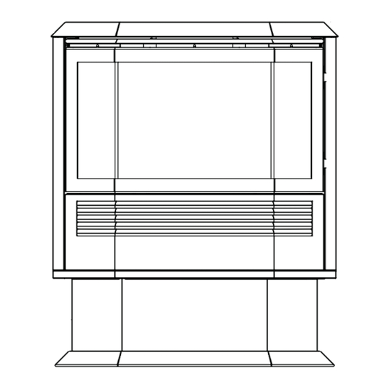
BAY WINDOW MANTIS SPECIFICATIONS Bay Window Mantis with Pedestal and Single Flue Adaptor Figure 38 f i r e - p a r t s . c o m Bay Window Mantis without pedestal Figure 39 Bay Window Mantis Insert with Slim and Short Top Cover Kits and Flex Kits. Figure 40 Page 28 30259-9-1115... -
Page 29: Bay Window Mantis Specifications
BAY WINDOW MANTIS SPECIFICATIONS - (continued) Bay Window Mantis Fireplace with PVE-1 Mantel Surround with PV-2H Slim Top Cover Kit Figure 41 f i r e - p a r t s . c o m Bay Window Mantis Fireplace with PVE-1 Mantel Surround with PV-4H Short Top Cover Kit Figure 42 Rear View Figure 43... -
Page 30: Fireplace Mantis Specifications
FIREPLACE MANTIS SPECIFICATIONS Figure 44 Figure 47 Fireplace - 42-7/8 inch Louverless Surround Kit f i r e - p a r t s . c o m Figure 48 Fireplace In Wall - 35 Inch Picture Frame Surround Figure 45 front Figure 49 Figure 46... - Page 31 FIREPLACE MANTIS SPECIFICATIONS Figure 50 Fireplace Mantis with 38 Inch Surround f i r e - p a r t s . c o m Figure 51 Clearance for Access Panel In-Wall Units See Gas Connection Instructions. Figure 52 30259-9-1115 Page 31...
-
Page 32: Gas Connection Installation
GAS CONNECTION INSTALLATION GAS SUPPLY LINE TO FIREPLACE CAUTION under conditions which will allow for easy removal Under no circumstances should the gas supply line f i r e - p a r t s . c o m Figure 54 - Bay Window Mantis Figure 53 - Fireplace Mantis Gas Connection - In-Wall Units - Fireplace Mantis ONLY removing three screws as shown in Figure 54. -
Page 33: Bay Window Mantis Log Set Installation Instructions
BAY WINDOW MANTIS LOG SET INSTALLATION INSTRUCTIONS Log Installation CAUTION Do not handle these logs with your bare hands! Always wear gloves to prevent skin irritation. After handling the logs, wash your hands gently with soap and water. Figure 58 Firebox Layout f i r e - p a r t s . -
Page 34: Bay Window Mantis Log Set Installation Instructions
BAY WINDOW MANTIS LOG SET INSTALLATION INSTRUCTIONS REAR LEFT LOG (A) TOP LEFT LOG (F) TOP RIGHT LOG (G) REAR RIGHT LOG (B) FRONT LEFT LOG (C) FRONT RIGHT LOG (E) CENTER LOG (D) Log Assembly Figure 62 Figure 60 f i r e - p a r t s . -
Page 35: Fireplace Mantis Log Set Installation Instructions
FIREPLACE MANTIS LOG SET INSTALLATION INSTRUCTIONS Log Installation CAUTION Figure 64. Do not handle these logs with your bare hands! Always wear gloves to prevent skin irritation. After handling the logs, wash your hands gently with soap and water. Log Placement Figure 63. -
Page 36: Wiring
WIRING WARNING plug for your protection against shock hazard and should be plugged directly into a properly grounded three-prong recep- tacle. Do not cut or remove the grounding prong from this injury. Take precautions to reduce such risks. plug. CAUTION Label all wires prior to disconnection when servicing controls. -
Page 37: Start Up Check List
START UP CHECK LIST WARNING BEFORE OPERATING THIS Fireplace, CARE- FULLY READ THE FOLLOWING. will not operate properly. f i r e - p a r t s . c o m lighting instructions. Refer to Page 38. Note: 30259-9-1115 Page 37... -
Page 38: Lighting Instructions
LIGHTING INSTRUCTIONS FOR YOUR SAFETY READ BEFORE LIGHTING WARNING: IF YOU DO NOT FOLLOW THESE INSTRUCTIONS EXACTLY, A FIRE OR EXPLOSION MAY RESULT CAUSING PROPERTY DAMAGE, PERSONAL INJURY, OR LOSS OF LIFE. B. Use on-the-wall switch remote con- WHAT TO DO IF YOU SMELL GAS tions. -
Page 39: Start Up And Adjustments
START UP AND ADJUSTMENTS Sequence of Operations – Front and Back Burners Figure 69 f i r e - p a r t s . c o m Figure 71 CAUTION When switching from one burner to the other burner, be “OFF”... -
Page 40: Start Up And Adjustments
START UP AND ADJUSTMENTS High Altitude Sequence of Operations – One Burner Only Paint Curing - First Firing CAUTION will soften during the initial operation, and will harden f i r e - p a r t s . c o m over time. -
Page 41: Frbtc Remote Instructions
FRBTC REMOTE INSTRUCTIONS INTRODUCTION Review COMMUNICATION SAFETY SECTION THERMOSTAT SAFETY SECTION f i r e - p a r t s . c o m KEY SETTINGS DISPLAY °F OR °C FLAME ROOM TEMP 30259-9-1115 Page 41... - Page 42 FRBTC REMOTE INSTRUCTIONS SETTING °F / °C SCALE °F. To change this setting to ° • Press the ON same time this will change from °F to ° ° °F. MANUAL FUNCTION ON OPERATION Press the ON (Flame icon will appear on LCD screen in on mode) OFF OPERATION f i r e - p a r t s .
- Page 43 FRBTC REMOTE INSTRUCTIONS OPERATIONAL NOTES: °F (1° REMOTE RECEIVER CAUTION: THE REMOTE RECEIVER SHOULD BE POSITIONED WHERE AMBIENT TEMPERATURES DO NOT EXCEED 130° F. f i r e - p a r t s . c o m from the trans- mitter.
- Page 44 FRBTC REMOTE INSTRUCTIONS CP (CHILDPROOF) FEATURE from the TRANSMITTER. SETTING “LOCK-OUT” –(CP) NOTE will not THERMOSTAT UPDATING FEATURE –TRANSMITTER – (T/S –TX) The transmitter normally reads the ROOM temperature every 2 minutes checking the ROOM temperature against the SET tem- f i r e - p a r t s .
- Page 45 FRBTC REMOTE INSTRUCTIONS THERMOSTAT SAFETY FEATURE – RECEIVER (T/S –RX) ° tion. ° ° inside the receiver case, reaches 130° ° ° the MODE f i r e - p a r t s . c o m ° °F. °F.
-
Page 46: Frbtc Remote Instructions
FRBTC REMOTE INSTRUCTIONS BATTERY LIFE TROUBLE SHOOTING ° 130° F. f i r e - p a r t s . c o m RECEIVER ADJUSTMENT – RECOMMENDED ADJUSTMENT SPECIFICATIONS Page 46 30259-9-1115... -
Page 47: Automatic Humidifier Operation
AUTOMATIC HUMIDIFIER OPERATION Note: Figure 73 f i r e - p a r t s . c o m 30259-9-1115 Page 47... -
Page 48: Optional Controls
OPTIONAL CONTROLS Economy Mode (Red Button Operation) Battery Operated Controls Optional Battery Operated Control FRBTP mostat Note: These optional controls will work with the factory installed receiver. No wiring is required. CAUTION Figure 74 Before connecting any controller, disconnect power f i r e - p a r t s . -
Page 49: Maintenance & Service
MAINTENANCE & SERVICE Resetting the Fireplace Cleaning the Glass Door WARNING Take precautions to reduce such risks CAUTION CAUTION Label all wires prior to disconnection when servicing Do not attempt to clean the glass when it is hot. Do controls. Wiring errors can cause improper and dangerous not strike or hit the glass. - Page 50 MAINTENANCE & SERVICE Circulating Air Blower Heat Exchanger Filter Figure 77 f i r e - p a r t s . c o m Figure 78 Figure 79 Page 50 30259-9-1115...
-
Page 51: Maintenance & Service
MAINTENANCE & SERVICE RECOMMENDED MAINTENANCE FREQUENCY OF MAINTENANCE MAINTENANCE ITEM MONTHLY BY ANNUALLY BY HOMEOWNER SERVICE PERSON Clean the glass f i r e - p a r t s . c o m Figure 80 30259-9-1115 Page 51... -
Page 52: Bay Window Mantis Parts List
BAY WINDOW MANTIS PARTS LIST WARNING Use only manufacturer’s replacement parts. Use of any other parts could cause injury or death. INDEX INDEX PART NO. DESCRIPTION PART NO. DESCRIPTION 27072 REAR PANEL ASSEMBLY BRACKET ASSEMBLY (SPRING 21640 21654 21665 RIGHT SIDE DOOR ASSEMBLY REAR HEAT SHIELD 24831 ASSEMBLY... -
Page 53: Bay Window Mantis Parts List
BAY WINDOW MANTIS PARTS LIST WARNING Use only manufacturer’s replacement parts. Use of any other parts could cause injury or death. INDEX INDEX PART NO. DESCRIPTION PART NO. DESCRIPTION 26128 GAS LINE - FRONT PUMP ASSEMBLY 29355 M174 GASKET R10489 AIR PRESSURE SWITCH 11269 GAS LINE BRACKET... -
Page 54: Bay Window Mantis Parts View
BAY WINDOW MANTIS PARTS VIEW f i r e - p a r t s . c o m Page 54 30259-9-1115... - Page 55 BAY WINDOW MANTIS PARTS VIEW f i r e - p a r t s . c o m 30259-9-1115 Page 55...
-
Page 56: Fireplace Mantis Parts List
FIREPLACE MANTIS PARTS LIST WARNING Use only manufacturer’s replacement parts. Use of any other parts could cause injury or death. INDEX NO. PART NO. DESCRIPTION INDEX NO. PART NO. DESCRIPTION 25207 PANEL - TOP SUMP ASSEMBLY 26088 21595 CONDENSATE TRAY FLEX PIPE ASSEMBLY 25223 LOUVER - TOP... -
Page 57: Fireplace Mantis Parts View
FIREPLACE MANTIS PARTS VIEW f i r e - p a r t s . c o m 30259-9-1115 Page 57... -
Page 58: Master Parts Distributor List
MASTER PARTS DISTRIBUTOR LIST Dey Distributing Victor Division of F. W. Webb Company 200 Locust Street Phone: 651-490-9191 Phone: 860-722-2433 Toll Free: 800-397-1339 Toll Free: 800-243-9360 Website: Fax: 860-293-0479 Parts: Heater, Hearth and Grills Toll Free Fax: 800-274-2004 Websites: Parts: Heater, Hearth and Grills East Coast Energy Products 10 East Route 36 f i r e - p a r t s . -
Page 59: Warranty
WARRANTY Limited Lifetime Parts Warranty – Factory-Installed Glass Limited Ten-Year Parts Warranty – Combustion Chamber Limited Five-Year Parts Warranty – All Other Components (Except Thermostats) Limited Two-Year Labor Warranty – All Components (Except Remote Controls, Thermostats) Limited One-Year Parts Warranty – Remote Controls, Thermostats f i r e - p a r t s . - Page 60 f i r e - p a r t s . c o m EMPIRE EMPIRE Comfort Systems www.empirecomfort.com Page 60 30259-9-1115...
Need help?
Do you have a question about the Mantis Series and is the answer not in the manual?
Questions and answers