Table of Contents
Advertisement
Advertisement
Table of Contents
Troubleshooting

Related Manuals for Datalogic Accu-Sort AccuVision AV6010


Summary of Contents for Datalogic Accu-Sort AccuVision AV6010
- Page 1 AV6010 ® AccuVision Long-Range Camera System Manual...
- Page 2 No patent liability is assumed by Accu-Sort (Datalogic) with respect to use of information, circuits, equipment, or software described in this manual. In no event will Datalogic Automation, Inc. be responsible or liable for indirect or consequential damages resulting from the use or application of this equipment.
-
Page 3: Table Of Contents
AccuVision AV6010 Long-Range Camera System Manual Contents ® Contents Preface Intended Audience ....................vii Other Sources of Information .................. vii Conventions ......................viii Customer Service ....................viii 1 Introduction Product Overview....................9 AV6010 Camera Module..................10 Distributed Computing Module (DCM) ..............11 RangeFinder Module..................... - Page 4 AccuVision AV6010 Long-Range Camera System Manual Contents ® Power Requirements / Power Supply Connections ..........54 Power Distribution Box for Multi-Camera Systems..........55 RangeFinder Power Supply Connection ..............56 AV6010 SYNC Network ..................57 Ethernet Communications Connections (Host & Image Networks) ......59 RS232/422 Serial Communications Connections (Host &...
- Page 5 AccuVision AV6010 Long-Range Camera System Manual Contents ® Side-by-Side Package Detection Setup and Calibration......... 104 Setup Camera Image Viewer ................ 105 Setup for Transport Type ................106 Capture Images .................... 107 Evaluate Images ................... 107 Optimize SBS Calibration ................108 Connecting to the IMAGE Network ..............
- Page 6 AccuVision AV6010 Long-Range Camera System Manual Contents ® Appendices A Specifications ..................... 147 Power Consumption Estimates ................148 RangeFinder Dimensions ..................148 AV6010 Camera Dimensions ................149 Read Charts ......................150 Certifications ....................... 151 B AV6010 User Interface ..................153 Setup ........................
-
Page 7: Intended Audience
AccuVision AV6010 Long-Range Camera System Manual Preface ® 1 Preface ® The AccuVision AV6010 Long-Range Camera System Manual from Accu-Sort Systems, Inc. includes the information you need to effectively integrate the AV6010 Camera System with your application. It contains detailed information about the following: Product features, capabilities, specifications and accessories Safety information Installation guidelines and procedures... -
Page 8: Conventions
viii Preface AccuVision AV6010 Long-Range Camera System Manual ® Conventions WARNINGS or CAUTIONS: This symbol identifies a hazard or procedure that, if incorrectly performed, could cause personal injury or result in equipment damage. It is also used to bring the user’s attention to details that are considered IMPORTANT. -
Page 9: Introduction
AccuVision AV6010 Long-Range Camera System Manual Chapter 1 ® 1 Introduction ® This section presents a detailed description of the AccuVision AV6010 Long-Range Camera Systems. It begins with a product overview. The system’s features are described in detail. System Overview User Interface Ordering Options and Accessories Product Overview... -
Page 10: Av6010 Camera Module
AccuVision AV6010 Long-Range Camera System Manual Introduction ® Camera Module The camera module includes the following key components: LED Illumination Camera Head Distributed Computing Module (DCM) Figure 1-2: AccuVision AV6010 Camera Module The LED illumination floods the scanning area with light as packages are conveyed past the AV6010 camera(s). -
Page 11: Distributed Computing Module (Dcm)
AccuVision AV6010 Long-Range Camera System Manual Chapter 1 ® Distributed Computing Module (DCM) The DCM includes the main processor, up to three COM Express (COM-e) modules (one standard, used for bar code decoding), and all the Ethernet/serial and parallel communications interfaces required by the system. -
Page 12: Rangefinder Module
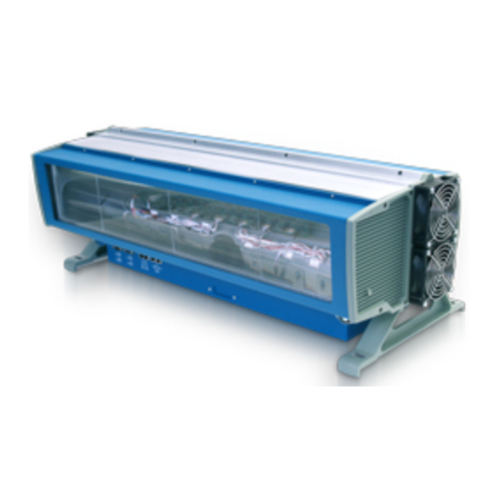
AccuVision AV6010 Long-Range Camera System Manual Introduction ® RangeFinder Module The RangeFinder module includes the following: RangeFinder Module RangeFinder Power Supply Mounting and adjustment brackets Figure 1-3: RangeFinder for AV6010 Camera Systems The RangeFinder is used to detect the presence of products as they enter the scanning area as well as report the package positions/heights and sequence number to all cameras in the system. -
Page 13: Av6010 User Interface
AccuVision AV6010 Long-Range Camera System Manual Chapter 1 ® AV6010 User Interface The AV6010 uses a browser-based application that lets you configure the system through a series of intuitive, user-friendly menus, tools and dialog boxes. Context sensitive help is available to assist with use of the application. -
Page 14: Typical Accuvision Av6010 Long-Range Camera Applications
AccuVision AV6010 Long-Range Camera System Manual Introduction ® Typical AccuVision AV6010 Long-Range Camera Applications Use the AV6010 in the following AccuVision Long-Range Camera System applications: single-camera applications multiple-camera scanning arrays (3-sided) Complete camera scanning tunnels (up to 6 sides) quadrant scanning tunnels Figure 1-5: Top-read Single-camera Application Accu-Sort Systems, Inc. - Page 15 AccuVision AV6010 Long-Range Camera System Manual Chapter 1 ® A three-sided scanning array is used to read bar codes on the top and sides of packages. When three or more cameras are used, a Power Distribution Box (PDB) is typically designed into the system. Figure 1-6: Scanning Tunnel –...
- Page 16 AccuVision AV6010 Long-Range Camera System Manual Introduction ® Figure 1-7: Scanning Tunnel – 5-Sided Application Figure 1-8: Tunnel Option – Bottom Read Application Accu-Sort Systems, Inc. 01-AV6010_Introduction_R10.doc...
- Page 17 AccuVision AV6010 Long-Range Camera System Manual Chapter 1 ® Quadrant scanning is used to assure high read rates on higher-density bar codes when packages passing through the tunnel are significantly skewed. Figure 1-9: Quadrant Scanning Tunnel Application 01-AV6010_Introduction_R10.doc Accu-Sort Systems, Inc.
-
Page 18: Dimensioning Applications
AccuVision AV6010 Long-Range Camera System Manual Introduction ® Dimensioning Applications Any AV6010 camera system with a top-read camera can be configured for the optional product dimensioning application. The DCM is equipped with a second COM-e module to enable the in-camera dimensioning functionality. The RangeFinder used in dimensioning applications is calibrated for an accuracy of 0.1”, 0.2”... -
Page 19: Rie / Ocr Applications
AccuVision AV6010 Long-Range Camera System Manual Chapter 1 ® RIE / OCR Applications Any AV6010 camera system can be equipped with an additional COM-e module in the DCM to enable the optional RIE (Raw Image Export) for use in OCR (Optical Character Recognition) applications. Side-by-Side Package Detection Applications An AV6010 camera system can be registered to use the side-by-side package detection option. - Page 20 AccuVision AV6010 Long-Range Camera System Manual Introduction ® Notes: Accu-Sort Systems, Inc. 01-AV6010_Introduction_R10.doc...
-
Page 21: Safety
AccuVision AV6010 Long-Range Camera System Manual Chapter 2 ® 2 Safety Please follow the safety precautions and warnings found in this manual when installing, setting up, operating, maintaining, troubleshooting or replacing any Accu-Sort products, parts, or related equipment. Following these precautions will prevent personal injury or damage to the unit. -
Page 22: Unpacking, Mounting And Installation Recommendations
AccuVision AV6010 Long-Range Camera System Manual Safety ® Unpacking, Mounting and Installation Recommendations CAUTION: Firmly fasten mounting structures in place before installing the equipment to any mounting structure. Avoid using freestanding mounting structures. If your application requires a freestanding mounting structure, avoid making the structure top-heavy. -
Page 23: Electrical Safety
AccuVision AV6010 Long-Range Camera System Manual Chapter 2 ® Electrical Safety AV6010 Camera must be installed in accordance with Canadian Electrical Code, Part I, CSA C22.1; CSA C22.2 No. 0; and the National Electrical Code, NFPA 70. For complete requirements, National Electrical Code, ANSI/NFPA 70, Canadian Electrical Code, Part I, C22.1, or other national standard must be consulted. -
Page 24: Electrostatic Discharge
AccuVision AV6010 Long-Range Camera System Manual Safety ® Electrostatic Discharge ESD CAUTION: Measures must be taken to prevent Electrostatic Discharge (ESD) at all times when handling any product, equipment, unit or part (e.g. use a grounded ESD wrist strap). It should be noted that circuit boards are at greatest risk to damage from ESD. -
Page 25: Laser/Led Safety
AccuVision AV6010 Long-Range Camera System Manual Chapter 2 ® Laser/LED Safety The AV6010 Camera Module uses visible red LEDs to create an “area flood pattern.” Do not stare into the camera’s exit window at the LED light. Avoid direct eye exposure. The LED light level does not constitute a health hazard, however staring at the LED light for prolonged periods could result in eye damage. - Page 26 AccuVision AV6010 Long-Range Camera System Manual Safety ® AV6010 RangeFinder Module Safety Label Locations Accu-Sort Systems, Inc. 02-AV6010_Safety_R10.doc...
-
Page 27: Mechanical Installation
AccuVision AV6010 Long-Range Camera System Manual Chapter 3 ® 3 Mechanical Installation IMPORTANT: The AV6010 contains electronics that may be affected by electrostatic discharge (ESD). To prevent personal injury or damage to the unit, please follow the safety precautions and warnings found in Chapter 2. Failure to follow these precautions may void your warranty. -
Page 28: Installation Sequence
AccuVision AV6010 Long-Range Camera System Manual Mechanical Installation ® Installation Sequence NOTE: Everything should be MECHANICALLY INSTALLED before performing any ELECTRICAL INSTALLATION. See Chapter 4 for electrical installation details. Installing a Single Camera System To install a single camera system, follow this sequence of steps: Complete mechanical installation. -
Page 29: Installing A Multiple Camera Tunnel
AccuVision AV6010 Long-Range Camera System Manual Chapter 3 ® Installing a Multiple Camera Tunnel To install a multiple camera system, follow this sequence of steps: Complete mechanical installation. Review the details of your application’s requirements. Determine and mark the mounting location. If an Accu-Sort structure is used, mounting locations are pre-marked. -
Page 30: General Mounting Guidelines
AccuVision AV6010 Long-Range Camera System Manual Mechanical Installation ® General Mounting Guidelines As you plan the installation of the AV6010 Camera(s) and RangeFinder, be sure to keep the following guidelines in mind: Determine the proper AV6010 orientation and position as it relates to the scanning area and transport direction. -
Page 31: Mounting Structure Assembly
AccuVision AV6010 Long-Range Camera System Manual Chapter 3 ® Mounting Structure Assembly When a mounting structure is supplied by Accu-Sort, a set of drawings is provided that supplies details specific to the applications. Accu-Sort mounting structures are designed to support from one to six cameras in a tunnel configuration. - Page 32 AccuVision AV6010 Long-Range Camera System Manual Mechanical Installation ® Column Type 1 Column Type 2 (qty. 2) (qty. 2) Right back / Left front Left back / Right front Side Rails (qty. 4) – Long, unmarked Cross Members (qty. 6) – Short, pre-marked Inner Side Rails qty.
- Page 33 AccuVision AV6010 Long-Range Camera System Manual Chapter 3 ® Flat Camera Sleds qty. 1 per camera) 45-degree Camera Sleds (optional, used in place of flat sled and mirror/sled) Mirror Sleds (qty. 1 per camera) (Use with all cameras that have a flat sled.) (enlarged view) T-Stud and Flanged Nut (pre-assembled, bulk quantity, large bag)
- Page 34 AccuVision AV6010 Long-Range Camera System Manual Mechanical Installation ® Assembly of side rails and cross members to columns Reference drawing 110425 for details on the mounting base (foot)) Installation of corner braces Accu-Sort Systems, Inc. 03-AV6010_Mechanical_Installation_R10.doc...
-
Page 35: Equipment Mounting
AccuVision AV6010 Long-Range Camera System Manual Chapter 3 ® Equipment Mounting Complete camera system equipment installation: Camera Module(s) (up to 6) Focus Mirror(s) (up to 6) RangeFinder Module Tachometer Power Distribution Box Others (Options) NOTE: If your application uses an Accu-Sort mounting structure, the positions of the RangeFinder, camera sleds and mirror sleds are pre-marked to simplify installation. -
Page 36: Camera Installation
AccuVision AV6010 Long-Range Camera System Manual Mechanical Installation ® Camera Installation Prerequisites: A flat surface (preferably the conveyor belt) Application specifications and mounting structure drawings Determine camera position and reading direction Tools Required: Socket driver (1/2”) battery powered (recommended) Tools (optional): Tape measure To install a Front/Top/Back camera: 1. - Page 37 AccuVision AV6010 Long-Range Camera System Manual Chapter 3 ® To install a Side/Quadrant camera: IMPORTANT: Depending on the application, the side-read camera may be installed on the inside of the mounting structure rather than the outside. Check your application structure drawings before mounting the side-read camera or mirror.
- Page 38 AccuVision AV6010 Long-Range Camera System Manual Mechanical Installation ® To install a Bottom-read camera: 1. Underneath the conveyor, place the camera on the sled, aligning the camera mounting feet with the alignment marks. 2. Attach with front-loading hardware. Do not over-tighten, which allows for adjustment during setup (if necessary), but assure the camera will not slide in the sled’s channel when it is lifted into position.
-
Page 39: Mirror Installation
AccuVision AV6010 Long-Range Camera System Manual Chapter 3 ® Mirror Installation Prerequisites: A flat surface (preferably the conveyor belt) Application specifications and mounting structure drawings Determine mirror position as it relates to the camera and reading direction Remember: Mirrors must be angled toward the conveyor. (Mirror adjustment to the correct angle is covered in Chapter 5.) Tools Required: Socket driver (1/2”) battery powered (recommended) - Page 40 AccuVision AV6010 Long-Range Camera System Manual Mechanical Installation ® To install a mirror for a Front/Top/Back camera: 1. Place the mirror assembly onto the mirror sled in the position marked. (Some mirror sleds are the same length as the mirror assembly, in which case there will be no marks.) 2.
- Page 41 AccuVision AV6010 Long-Range Camera System Manual Chapter 3 ® To install a mirror for a Side/Quadrant camera: IMPORTANT: Depending on the application, the side-read camera may be installed on the inside of the mounting structure rather than the outside. Check your application structure drawings before mounting the side-read camera or mirror.
- Page 42 AccuVision AV6010 Long-Range Camera System Manual Mechanical Installation ® To install a mirror for a Bottom read camera: 1. Place the mirror assembly onto the mirror sled in the position marked. (Some mirror sleds are the same length as the mirror assembly, in which case there will be no marks.) 2.
-
Page 43: Rangefinder Installation
AccuVision AV6010 Long-Range Camera System Manual Chapter 3 ® RangeFinder Installation Prerequisites: None. Tools Required: Socket driver (1/2”) Allen wrench (5/32”) 1. Attach mounting brackets to both sides of RangeFinder (if not already installed). 2. Assure RangeFinder is positioned facing in the correct direction. 3. -
Page 44: Mounting The Tachometer
AccuVision AV6010 Long-Range Camera System Manual Mechanical Installation ® Mounting the Tachometer The tachometer (tach) option outputs a set number of pulses for each wheel rotation. This tells the AV6010 the precise conveyor speed, allowing it to determine the exact package position. Tracking allows for multiple boxes to be in the scanning area at the same time. -
Page 45: Mounting The Trigger Photoeye
AccuVision AV6010 Long-Range Camera System Manual Chapter 3 ® Mounting the Trigger Photoeye The standard photoeye works by bouncing a light beam off a reflector and detecting when something breaks the path of light. In order for photoeyes to work properly, make sure the following things are done when mounting the trigger photoeye option: Mount trigger and reflector so the reader’s scan beam does not strike either of them. -
Page 46: Mounting The Light Curtain
AccuVision AV6010 Long-Range Camera System Manual Mechanical Installation ® Mounting the Light Curtain For installations that use the light curtain option, see the application-specific drawing for mounting details. See also the documentation provided with the light curtain. See wiring information in Chapter 4. Mounting the Photoeye/Tach Generator Box For installations that use the Photoeye/Tach Generator Box option (e.g., tilt- tray applications), see the application-specific drawing for mounting details. -
Page 47: Electrical Installation
AccuVision AV6010 Long-Range Camera Manual Chapter 4 ® 4 Electrical Installation WARNING: Electrical installation by qualified service technicians only! A trained technician must perform any procedures involving potential exposure to high voltage electricity. Do not attempt to perform any electrical installation procedures unless you are a trained technician. -
Page 48: Installing A Single Camera System
AccuVision AV6010 Long-Range Camera Manual Electrical Installation ® Installing a Single Camera System Prerequisites: Complete preparations for electrical installation (see page 47) Cabling (supplied with equipment) Channel locks (for holding cables inside structure channels) (supplied with structure) Single-camera system interconnect drawing 112754 in Appendix I ... - Page 49 AccuVision AV6010 Long-Range Camera Manual Chapter 4 ® 5. Connect one of the RangeFinder’s SYNC ports to the camera’s SYNC 6. Connect the other RangeFinder SYNC port to the camera’s SYNC OUT. 7. Connect the tachometer to the camera’s TACH port (if required). (Do NOT connect the tachometer to the RangeFinder’s TACH port.) 8.
-
Page 50: Installing A Multiple Camera Tunnel
AccuVision AV6010 Long-Range Camera Manual Electrical Installation ® Installing a Multiple Camera Tunnel Prerequisites: Complete preparations for electrical installation (see page 47) Cabling (supplied with equipment, may be color coded) Channel locks (for holding cables inside structure channels) ... - Page 51 AccuVision AV6010 Long-Range Camera Manual Chapter 4 ® 4. Connect the photoeye to the designated camera’s TRIG port (if required). 5. AC power: Connect the RangeFinder, cameras and all other devices to the AC power source. Typically an Accu-Sort Power Distribution Box (PDB) is used.
-
Page 52: General Electrical Installation Guidelines And Precautions
AccuVision AV6010 Long-Range Camera Manual Electrical Installation ® General Electrical Installation Guidelines and Precautions It is important that you follow these general precautions when installing, setting up, operating, maintaining, troubleshooting or replacing any Accu- Sort products, parts or related equipment. As you plan and install your AV6010, be sure to keep the following guidelines in mind: Determine the AV6010 is in the proper location as outlined in Chapter 3. -
Page 53: Wiring The Av6010
AccuVision AV6010 Long-Range Camera Manual Chapter 4 ® Wiring the AV6010 After completing mechanical installation, use this section to properly wire your AV6010 for optimal performance in your application. All wiring connections to the AV6010 are made to the connector panel. Determine the wiring connections needed for your application. -
Page 54: Power Requirements / Power Supply Connections
AccuVision AV6010 Long-Range Camera Manual Electrical Installation ® Ethernet Cable Snap-On Ferrite Placement of Snap-On Ferrites on Cables To Attach the Ferrites: Snap two ferrites to each Ethernet or serial cable like those shown in the image on page 1. Place the ferrites approximately the distance shown from the end of the cable (close to the AV6010). -
Page 55: Power Distribution Box For Multi-Camera Systems
AccuVision AV6010 Long-Range Camera Manual Chapter 4 ® Power Distribution Box for Multi-Camera Systems Applications using two or more cameras will use the Power Distribution Box (PDB, 111063) to handle power for the RangeFinder, up to six cameras and the optional VisionCapture/Image Depot Server (IDS). POWER INLET (4-Wire Grounded) 30 AMP 125/250 VAC... -
Page 56: Rangefinder Power Supply Connection
AccuVision AV6010 Long-Range Camera Manual Electrical Installation ® RangeFinder Power Supply Connection RangeFinder power supply connection procedure: 1. Connect the power supply DC input connector into the RangeFinder’s PWR IN (DC input). 2. Plug the AC power cord into the power supply. -
Page 57: Av6010 Sync Network
AccuVision AV6010 Long-Range Camera Manual Chapter 4 ® AV6010 SYNC Network The AV6010 Camera System uses Ethernet communications for a dedicated SYNC network. Only AV6010 cameras and the RangeFinder may be connected to the SYNC network. See the interconnect drawings for a single- camera (112754) and multi-camera system (112753) in Appendix I. - Page 58 AccuVision AV6010 Long-Range Camera Manual Electrical Installation ® Connecting Camera to Camera: In applications where there are two or more cameras, the SYNC network forms a ‘ring network’ that starts and ends with the RangeFinder. (See drawing 112753 in Appendix I.) Connections between cameras should be made as follows: 1.
-
Page 59: Ethernet Communications Connections (Host & Image Networks)
AccuVision AV6010 Long-Range Camera Manual Chapter 4 ® Ethernet Communications Connections The AV6010 uses Ethernet for LAN (local area network) communications. Ethernet communications cabling can be run up to 330 feet [100 meters]. See interconnection drawings 112753 and 112754 in Appendix I. HOST Network IMAGE Network Connecting a Host or Image Network:... -
Page 60: Rs232/422 Serial Communications Connections (Host & Focus)
AccuVision AV6010 Long-Range Camera Manual Electrical Installation ® RS232/422 Serial Communications Connections The AV6010 provides two standard RS232/422 serial ports identified as HOST and FOCUS. Use RS232 for a direct connection to a controller, personal computer, or other device. HOST (Serial Port) FOCUS (Serial Port) RS232 provides point-to-point communications at distances up to ... -
Page 61: Tachometer And Trigger Connections
AccuVision AV6010 Long-Range Camera Manual Chapter 4 ® TACHOMETER and TRIGGER Connections If your system includes the TACH or TRIG options, be sure to use the provided cables to make the necessary connections. In multi-camera networks, these connections are made to only one camera. That camera is considered to be the ‘controller’... -
Page 62: Check Av6010 Installation
AccuVision AV6010 Long-Range Camera Manual Electrical Installation ® Check AV6010 Installation After completing the installation of your AV6010: Confirm that the AV6010 has been properly installed mechanically and electrically. Use the Installation Sequence at the beginning of this chapter and your application specifications to check your installation. All interconnections should match the drawing that is applicable to your ... -
Page 63: Setup
AccuVision AV6010 Long-Range Camera System Manual Chapter 5 ® 5 Setup This chapter provides details on how set up the AV6010 Long-Range Camera System for your application. It outlines how to: Auto calibrate the system to your application Define the symbologies your system will decode Configure the communications between the system and host After configuring your system using the browser-based AV6010 User Interface and AV6010 Install Wizard, use the operations checklist in... -
Page 64: Setup System Requirements
AccuVision AV6010 Long-Range Camera System Manual Setup ® Setup System Requirements The laptop computer you use to setup the AV6010 Camera System should meet the following requirements: Category Description Basic Configuration Windows XP Operating System Ethernet port/NIC Card for using Install Wizard Microsoft .NET framework (see page 94) ®... -
Page 65: First-Time Setup Checklist
AccuVision AV6010 Long-Range Camera System Manual Chapter 5 ® First-Time Setup Checklist Basic Setup 1. Confirm that all equipment is mechanically and electrically installed properly. (See Chapters 3 and 4.) 2. Unlock camera head and align the mirror. (In multi-camera tunnels, confirm the power switch is ON.) 3. -
Page 66: Unlock The Av6010 Camera Head
AccuVision AV6010 Long-Range Camera System Manual Setup ® Unlock the AV6010 Camera Head 1. Locate the shipping screw on the camera. 2. Using a flat head screwdriver, turn the camera head shipping lock to the unlocked position. Only turn 1/4 turn counter-clockwise. Do not force the shipping screw beyond the 1/4 turn. -
Page 67: Mirror Alignment
AccuVision AV6010 Long-Range Camera System Manual Chapter 5 ® Mirror Alignment Before using any of the camera calibration wizards, you will need to: Install the folding mirrors Determine proper mirror angles Confirm proper mirror alignment for the camera position. Remove the protective film from the mirror surface. Prerequisites: Before you begin, you will need: Mirror alignment tools (8, 15, and 45-degrees) 5/32”... -
Page 68: To Align A Mirror For Front, Top Or Back Applications
AccuVision AV6010 Long-Range Camera System Manual Setup ® To align a mirror for Front, Top or Back applications: 1. Confirm mirror is properly mounted to the mirror sled (as shown). The flanged edge of the mirror mounting brackets should face the camera and the mirror angle will be almost parallel with the flange. -
Page 69: To Align A Mirror For Side-Read Applications
AccuVision AV6010 Long-Range Camera System Manual Chapter 5 ® To align a mirror for Side Read applications: 1. Confirm mirror is properly mounted to the mirror sled (as shown). The flanged edge of the mirror mounting brackets should face the camera and the mirror angle will be almost perpendicular with the flange. -
Page 70: Leveling The Rangefinder
AccuVision AV6010 Long-Range Camera System Manual Setup ® Leveling the RangeFinder Before beginning normal operations, the RangeFinder must be level with the conveyor surface. This is especially important to dimensioning applications. WARNING: The RangeFinder uses visible red lasers and is rated as a Class 2 Laser Product. -
Page 71: Blocking Rangefinder Codewords On Narrow Belts
AccuVision AV6010 Long-Range Camera System Manual Chapter 5 ® Blocking RangeFinder Codewords on Narrow Belts In applications where the conveyor is less than 40-inches wide, it is necessary to block the RangeFinder laser pattern (also called codewords) that is projected beyond the edges of the conveyor. WARNING: The RangeFinder uses visible red lasers and is rated as a Class 2 Laser Product. -
Page 72: First-Time Startup: Single Camera
AccuVision AV6010 Long-Range Camera System Manual Setup ® First-time Startup: Single Camera 1. Make sure all AV6010 system components are connected to the correct power source. 2. To start the AV6010 camera(s), apply power using the power switch. 3. On initial power-up, the AV6010 performs an initialization sequence. 4. -
Page 73: First-Time Startup: Camera Tunnel Using Power Distribution Box
AccuVision AV6010 Long-Range Camera System Manual Chapter 5 ® First-time Startup: Camera Tunnel using Power Distribution Box Multi-camera applications, such as scanning arrays and tunnels, use the Power Distribution Box (PDB). The RangeFinder and all cameras are electrically wired to the PDB. 1. -
Page 74: First-Time Setup
AccuVision AV6010 Long-Range Camera System Manual Setup ® First-time Setup The AV6010 browser-based user interface is the tool you will use to setup, change parameters, monitor operations, and diagnose problems. To establish a connection and login: 1. Connect an Ethernet cable to your computer’s Ethernet port and to the AV6010 camera SYNC network (either IN or OUT) NOTE: You may need to disconnect a cable from one of these ports if an open one is not... -
Page 75: Confirm Computer Is Set Up For Dhcp
AccuVision AV6010 Long-Range Camera System Manual Chapter 5 ® How to confirm your computer is set up for DHCP: 1. Under Windows, go to the Start menu. 2. Select Control Panel > Network Connections and click Network Connections. 3. Click Local Area Connection. 4. -
Page 76: Av6010 User Interface System Configuration
AccuVision AV6010 Long-Range Camera System Manual Setup ® AV6010 User Interface System Configuration Use the System Configuration page to check that a connection is established with all AV6010 components in your system, assign a name to the system, and confirm (or set) the positions for each device. Prerequisites: None. -
Page 77: Tachometer
AccuVision AV6010 Long-Range Camera System Manual Chapter 5 ® Tachometer Use the Tachometer window to set key parameters that help define the camera system’s timing during normal operations. Prerequisites: You must know whether your system is using an external tachometer or will be requiring an internal tachometer setting for a specific number of feet per minute. -
Page 78: Focus And Detection
AccuVision AV6010 Long-Range Camera System Manual Setup ® Focus and Detection Use this window to set the key focusing and package detection requirements for your application. Prerequisites: You must know your application requirements for: minimum/maximum package sizes (length, width and height), package spacing, conveyor width (automatically set by the AV6010 Install Wizard), focus source and... -
Page 79: Rangefinder Mounting
AccuVision AV6010 Long-Range Camera System Manual Chapter 5 ® RangeFinder Mounting Use the RangeFinder Mounting window to make adjustments the orientation, mounting position and front/back box tracking extensions. NOTE: It is recommended that the AV6010 Install Wizard be used to set these parameters the first time. -
Page 80: Camera Mounting
AccuVision AV6010 Long-Range Camera System Manual Setup ® Camera Mounting Use the Camera Mounting window to make adjustments to the orientation, mounting position and front/back box tracking extensions. NOTE: It is recommended that the AV6010 Install Wizard be used to set these parameters the first time. -
Page 81: Symbologies
AccuVision AV6010 Long-Range Camera System Manual Chapter 5 ® Symbologies Use the Setup > Symbologies window to add, modify or delete any of the symbologies that the camera system must decode. A unique name may also be assigned to each symbology on the Active Symbologies list. Prerequisites: You will need to know the symbologies to be scanned and decoded by your system including: All symbology types to be ‘found’... -
Page 82: Deleting A Symbology
AccuVision AV6010 Long-Range Camera System Manual Setup ® Deleting a symbology: 1. Click on the option button to the left of the symbology to be deleted. 2. Click Remove. The selected symbology disappears from the Enabled Symbologies list. 3. Click Update. Modifying a symbology in the Selected Symbologies list: 1. -
Page 83: Communications Transmit Point
AccuVision AV6010 Long-Range Camera System Manual Chapter 5 ® Communications Transmit Point Use this window to set the transmit point for your application. In multiple camera / tunnel applications, each camera may have a unique transmit point setting. Prerequisites: You will need to know the serial communications details: Baud rate, stop bits, parity, data bits, flow control, transmit message type and keep alive message. -
Page 84: Serial Communications
AccuVision AV6010 Long-Range Camera System Manual Setup ® Serial Communications Use this window to set the serial communications requirements for your application. In multiple camera / tunnel applications, each camera may have unique serial communication settings, if needed. At the very least, the Transmit Point settings will be different. -
Page 85: Host Network
AccuVision AV6010 Long-Range Camera System Manual Chapter 5 ® Host Network Use this window to set the host network requirements for your application. Prerequisites: You will need to know the host network communications details: IP address, gateway and netmask Connection type Message format To set the Host Network: 1. -
Page 86: Image Network
AccuVision AV6010 Long-Range Camera System Manual Setup ® Image Network ® Some applications use the optional AccuVision VisionCapture™ Image Capture System to gather and store images. If your application utilizes the this system with an Image Depot Server (IDS), you will need to setup the Image Network screen. -
Page 87: Advanced > Imaging (Camera)
AccuVision AV6010 Long-Range Camera System Manual Chapter 5 ® Advanced > Imaging (Camera) CAUTION: Modifying any of these advanced parameters may adversely affect the operation of your camera system. Changes to these parameters should not be made unless recommended by an authorized Accu-Sort customer support technician. -
Page 88: Advanced > Decoder Options
AccuVision AV6010 Long-Range Camera System Manual Setup ® Advanced > Decoder Options CAUTION: Modifying the advanced parameters may adversely affect the operation of your camera system. Changes to these parameters should not be made unless recommended by an authorized Accu-Sort customer support technician. -
Page 89: Dimensioning Setup And Calibration
AccuVision AV6010 Long-Range Camera System Manual Chapter 5 ® Dimensioning Setup and Calibration Some applications use the optional AV6010 dimensioning module for dimension-weighing-scaling and / or revenue recovery applications. Prerequisites: You will need the following: Top-read camera must include a DCM with the dimensioning module All wizard calibrations must be completed (system “tracked in”) Dimensioning calibration box or calibration test patterns Laptop with Install Wizard connected to camera system... -
Page 90: Tachometer Settings For Dimensioning
AccuVision AV6010 Long-Range Camera System Manual Setup ® Top Camera Mounting Settings for Dimensioning 1. Select Setup > Mounting > Top from the menu tree. The Camera Mounting (Top) window is displayed. 2. Set the Camera Pitch Angle to 8.0 degrees. NOTE: The top-read camera’s mirror must be set for an angle of 8-degrees (±... -
Page 91: Dimensioning Settings
AccuVision AV6010 Long-Range Camera System Manual Chapter 5 ® Dimensioning Settings 1. Select Setup > Options > Dimensioning from the menu tree. The Dimensioning window is displayed. 2. Set the Package Height Options: a. Variation Threshold to 0.2 b. Accuracy to 0.2 inch. 3. -
Page 92: Calibrating The Dimensioning System
AccuVision AV6010 Long-Range Camera System Manual Setup ® Calibrating the Dimensioning System 1. Start the conveyor belt. Allow it to run for a few minutes until the RangeFinder has had time to SYNC with the cameras. 2. Select Diagnostics > System Status and confirm that all the cameras and RangeFinder are reporting OK. -
Page 93: Av6010 Install Wizard
AccuVision AV6010 Long-Range Camera System Manual Chapter 5 ® AV6010 Install Wizard Use the AV6010 Install Wizard application as a simplified method of determining the mounting information needed in the AV6010 user interface under the Mounting > Ranger and Mounting > Camera setup screens. Based on your application, there can be several auto calibration wizards made available through the AV6010 Install Wizard application including the RangeFinder and one for each camera in the system. -
Page 94: To Download The Microsoft .Net Framework
AccuVision AV6010 Long-Range Camera System Manual Setup ® NOTE: If your computer does not have the Microsoft's .NET framework installed, this error will display when you launch the AV6010 Install Wizard: To download the Microsoft .NET framework: 1. To find and install the Microsoft .NET framework needed in order to run the AV6010 Install Wizard go to: http://search.microsoft.com/results.aspx?mkt=en-US&setlang=en- US&q=.NET+framework... -
Page 95: To Open The Av6010 Install Wizard
AccuVision AV6010 Long-Range Camera System Manual Chapter 5 ® To open the AV6010 Install Wizard: 1. Locate the icon on your desktop. 2. Double-click the icon to open the wizard. 3. The AV6010 Install Wizard screen is displayed. 05-AV6010_Setup_R10.doc Accu-Sort Systems, Inc. -
Page 96: Rangefinder Wizard
AccuVision AV6010 Long-Range Camera System Manual Setup ® RangeFinder Wizard This wizard is used to learn the RangeFinder’s position over the conveyor, including the usable conveyor (region of interest) and height above the conveyor surface. Prerequisites: Calibration box Tape measure Confirm the RangeFinder is centered over the scanning area Confirm the RangeFinder is level and that excess codewords are blocked if the application is using a narrow belt (under 40-inches) - Page 97 AccuVision AV6010 Long-Range Camera System Manual Chapter 5 ® Left side of conveyor Direction of Travel Right side of conveyor RangeFinder’s scan line on conveyor, Close-up of the RangeFinder’s edges of usable belt shown scan line pattern (code words) RangeFinder Scan Line Measuring from edge of conveyor Close-up of measuring to the alignment dot...
-
Page 98: Photoeye Wizard
AccuVision AV6010 Long-Range Camera System Manual Setup ® Photoeye Wizard This wizard is used to setup a photoeye as the package detection / trigger source for the camera system. Prerequisites: Photoeye must be installed at the correct location a minimum of 6.0 inches [152 mm] upstream from the RangeFinder or light curtain. -
Page 99: Light Curtain Wizard
AccuVision AV6010 Long-Range Camera System Manual Chapter 5 ® Light Curtain Wizard This wizard is used to setup a light curtain as the trigger source. Prerequisites: Light curtain must be installed at the correct location (reference the installation drawings provided with the system) Light curtain must be set as both the focus and the package detection trigger on the Focus and Detection page of the AV6010 User Interface Tape measure... -
Page 100: Top Camera Wizard
AccuVision AV6010 Long-Range Camera System Manual Setup ® Top Camera Wizard This wizard is used to learn the Top camera’s position. Setup for Top, Top-Front or Top-Back cameras is similar. The icon will appear different based on the camera orientation. Prerequisites: Know the top camera angle required by the system. -
Page 101: Dimensioning Wizard
AccuVision AV6010 Long-Range Camera System Manual Chapter 5 ® Dimensioning Wizard This wizard is used to verify the AV6010 auto calibration for dimensioning. Prerequisites: You will need the following: All previous wizard calibrations must be completed Need the ASIDIM and ASICAL boxes Laptop with Install Wizard connected to camera system To run the Dimensioning wizard: 1. - Page 102 AccuVision AV6010 Long-Range Camera System Manual Setup ® Dynamic Focus Calibration Before beginning normal operations, the cameras need to be dynamically focused. Prerequisites: All cameras have been setup using the AV6010 Install Wizard Laptop must be connected to a camera’s IMAGE port (see Connecting to the IMAGE Network) AV6010 User Interface and Camera Image Viewer should both be open on the laptop’s desktop...
-
Page 103: Dynamic Focus Calibration
AccuVision AV6010 Long-Range Camera System Manual Chapter 5 ® To dynamically focus a camera: 1. Open the Camera Image Viewer. 2. In the View Menu, enable Show Extra Info, Plot FocusRange and Package Corner. 3. In the IDS Menu, be sure it is Enabled. 4. -
Page 104: Side-By-Side Package Detection Setup And Calibration
AccuVision AV6010 Long-Range Camera System Manual Setup ® Side-by-Side Package Detection Setup Prerequisites: Top Camera (mounted at +15 degrees or less) Software versions (AV6010 Camera v6.0 and RangeFinder v8.0) System has been properly setup with Install Wizard Confirm all application parameters are correctly entered in the AV6010 user interface (e.g., min and max box sizes) Image cropping lines properly set during initial camera setup Tools and Materials Required:... -
Page 105: Setup Camera Image Viewer
AccuVision AV6010 Long-Range Camera System Manual Chapter 5 ® Setup Camera Image Viewer 1. Launch the Camera Image Viewer. (To perform SBS setup, version 6.0 is required.) 2. In the View drop-down menu, select both Show Extra Information and View SBS Information. 3. -
Page 106: Setup For Transport Type
AccuVision AV6010 Long-Range Camera System Manual Setup ® Setup for Transport Type To set SBS to work with Belt Conveyors: 1. Select the Setup tab in the Image Viewer. 2. Select Black Conveyor Belt from the drop-down menu. 3. Select the Calibration tab. 4. -
Page 107: Capture Images
AccuVision AV6010 Long-Range Camera System Manual Chapter 5 ® Capture Images IMPORTANT: The objective is to collect images for a representative sample of the live freight running through the system. This sampling should include a full variety of packages representing typical product flow. Be sure this includes collecting images of SBS conditions. -
Page 108: Optimize Sbs Calibration
AccuVision AV6010 Long-Range Camera System Manual Setup ® Optimize SBS Calibration 1. On the Detection tab, use the SBS Detection Sensitivity slider bar to adjust sensitivity higher by one. (Default is 3.) 2. Click Process Images and Calculate Results. 3. The SBS Rate dialog box appears. Make a note of the percentages. 4. -
Page 109: Connecting To The Image Network
AccuVision AV6010 Long-Range Camera System Manual Chapter 5 ® Connecting to the IMAGE Network Before attempting to connect to a camera’s IMAGE port, you need to set the laptop computer’s static IP address as shown here. How to use a static IP address: 1. -
Page 110: Download Camera Image Viewer
AccuVision AV6010 Long-Range Camera System Manual Setup ® Download Camera Image Viewer To download and install the Camera Image Viewer: 1. Establish a connection with the AV6010 user interface. 2. Go to Diagnostics > Tools in the menu tree. The Tools screen is displayed. Under Downloads, click the Utilities and Documentation link. -
Page 111: Operations
AccuVision AV6010 Long-Range Camera System Manual Chapter 6 ® 6 Operations This chapter provides details on how the AV6010 Long-Range Camera System functions during normal operation. It also outlines how you can verify optimal performance through several methods: Become more familiar with your application Step-by-step start-up operations checklist Status Indicator LEDs AV6010 Camera... -
Page 112: Av6010 Startup
AccuVision AV6010 Long-Range Camera System Manual Operations ® AV6010 Startup 1. To start the AV6010, make sure it is connected to the power source and apply power using the power switch. In multi-camera applications, power may be controlled through the Power Distribution Box (PDB). 2. -
Page 113: To Quickly Check The Operation Of An Av6010 System
AccuVision AV6010 Long-Range Camera System Manual Chapter 6 ® To quickly check the operation of an AV6010 system: 1. Confirm properly completed installation as outlined in Chapters 3 and 4. 2. Apply power to the AV6010 and follow the startup procedure. 3. -
Page 114: Av6010 Camera Status Indicators
AccuVision AV6010 Long-Range Camera System Manual Operations ® AV6010 Camera Status Indicators Several status indicators are located on the DCM interface panel. Status Indicators – Normal Operations Indicator Description Solid Green - System okay STAT Solid Red - Error Blinking Red - Recoverable error (e.g., not all cameras responding) TRIG Indicates the camera system is receiving the TRIGGER signal. -
Page 115: Lan Communications Status Indicators
AccuVision AV6010 Long-Range Camera System Manual Chapter 6 ® LAN Communications Status Indicators 1 Gigabit LAN LED Status Indicators (1 Gigabit) Color LED State Description Left Green LAN link is not established. LAN link is established. Right Orange Modulates with data. 06-AV6010_Operations_R10.doc Accu-Sort Systems, Inc. -
Page 116: Camera Control Panel Buttons
AccuVision AV6010 Long-Range Camera System Manual Operations ® AV6010 Camera Control Panel Buttons Three buttons are located on the DCM interface panel. Button Description Upload Download Default – Push and hold "Up" and "Down" buttons simultaneously. STAT LED will start blinking rapidly while the buttons are being held. -
Page 117: Av6010 Rangefinder Status Indicators
AccuVision AV6010 Long-Range Camera System Manual Chapter 6 ® AV6010 RangeFinder Status Indicators Several status indicators are located on the RangeFinder interface panel. RangeFinder Status Indicators – Normal Operations Indicator Description Check Status of RangeFinder. System Ok (Green LED solid ‘ON’) System Standby (Green LED blinking) Standby condition indicates the conveyor has stopped or... -
Page 118: Checking Operations
AccuVision AV6010 Long-Range Camera System Manual Operations ® Checking Operations AV6010’s browser-based interface enables you to evaluate the operational performance of your AV6010 long-range camera system by providing vital statistics via status indicators, real-time read quality monitoring, and additional information. Outgoing and incoming messages are also monitored. Diagnostics Menu Tree of AV6010 Browser-based Application Diagnostics >... -
Page 119: Dimensioning Operations
AccuVision AV6010 Long-Range Camera System Manual Chapter 6 ® Dimensioning Operations During normal operations, if your AV6010 Camera System is also equipped to perform dimensioning, there are several functions that can be useful to monitor system status and check dimensioning data, including: Daily verification Viewing measurement data Dimensioning status... - Page 120 AccuVision AV6010 Long-Range Camera System Manual Operations ® To view the Audit Trail Log: 1. Login as a Monitor user. 2. Go to Diagnostics > Top > Logging. 3. Select Audit Trail Log and AATM Options. Remember: Times are GMT. 4.
-
Page 121: Side-By-Side Package Detection Operations
AccuVision AV6010 Long-Range Camera System Manual Chapter 6 ® Side-by-Side Package Detection Operations Once the system is properly configured for SBS package detection, it can be monitored from the Diagnostics > System Monitor. Seasonal changes in product flow may require calibration of additional SBS conditions. - Page 122 AccuVision AV6010 Long-Range Camera System Manual Operations ® Notes: Accu-Sort Systems, Inc. 06-AV6010_Operations_R10.doc...
-
Page 123: Maintenance
AccuVision AV6010 Long-Range Camera System Manual Chapter 7 ® 7 Maintenance This chapter provides instructions for maintaining optimum performance and life for your AV6010 Long-Range Camera System. It provides specific information on: Maintenance Procedures Exterior Cleaning Mounting Hardware Checks Wiring Connection Checks Maintenance Tools and Materials Needed Item Description... -
Page 124: Maintenance Tasks
AccuVision AV6010 Long-Range Camera System Manual Maintenance ® Maintenance Tasks Perform the maintenance tasks on an “as needed” basis to assure proper operation of the camera. Task schedule frequency depends upon the application environment conditions. Harsh environments that expose the equipment to more heat, dust, and dirt will require these procedures be performed more frequently. -
Page 125: Cleaning The Camera Window
AccuVision AV6010 Long-Range Camera System Manual Chapter 7 ® Cleaning the Camera Window WARNING: Shut down the camera system before performing this maintenance task. Do not stare into the camera’s window at the LED light. Avoid direct eye exposure. The LED light level does not constitute a health hazard, however staring at the LED light for prolonged periods could result in eye damage. -
Page 126: Cleaning The Folding Mirror
AccuVision AV6010 Long-Range Camera System Manual Maintenance ® Cleaning the Folding Mirror WARNING: Shut down the camera system before performing this maintenance task. Do not stare into the camera’s window at the LED light. Avoid direct eye exposure. The LED light level does not constitute a health hazard, however staring at the LED light for prolonged periods could result in eye damage. -
Page 127: Cleaning The Rangefinder Window
AccuVision AV6010 Long-Range Camera System Manual Chapter 7 ® Cleaning the RangeFinder Windows WARNING: Shut down the camera system before performing this maintenance task. Do not stare into the RangeFinder’s laser exit windows. Avoid direct eye exposure. The laser light level does not constitute a health hazard, however staring at the laser light for prolonged periods could result in eye damage. -
Page 128: Tighten Mounting Hardware
AccuVision AV6010 Long-Range Camera System Manual Maintenance ® Tighten Mounting Hardware The front-loading mounting hardware used to assemble the mounting structure and mount the equipment should not become lose if properly tightened. This is a safety check recommended for harsh environments where vibration may be a problem. -
Page 129: Troubleshooting
AccuVision AV6010 Long-Range Camera System Manual Chapter 8 ® 8 Troubleshooting This chapter provides instructions for diagnosing, troubleshooting and correcting AV6010 performance issues. It provides specific information on: Status Indicators Diagnostics Troubleshooting (Problem/Cause/Solution) Reference the content of this chapter for details on the diagnostics, tools and logs available for the system including: System Monitor RangeFinder Monitor... -
Page 130: Av6010 Camera Status Indicators
AccuVision AV6010 Long-Range Camera System Manual Troubleshooting ® Camera Status Indicators: Fault Detection Description STAT Status of camera system. (See Error Codes, Appendix F.) Warning (Status Red LED blinking, recoverable error) Error (Status Red LED solid ‘ON’) TRIG Trigger – No LED activity means system is not being triggered. TACH Tachometer –... -
Page 131: Av6010 Rangefinder Status Indicators
AccuVision AV6010 Long-Range Camera System Manual Chapter 8 ® RangeFinder Status Indicators: Fault Detection Laser 1 / DOE 1 Laser 2 / DOE 2 Description Status of RangeFinder. (See Error Codes, Appendix F.) Info (Green LED blinking) Status of RangeFinder. (See Error Codes, Appendix F.) Warning (Red LED blinking) Error... -
Page 132: Diagnostics
AccuVision AV6010 Long-Range Camera System Manual Troubleshooting ® Diagnostics A skilled technician can also use the AV6010 user interface application to perform specific diagnostics functions. Use the Diagnostics available from the user interface to check the following: System Status Images RangeFinder Status Camera Status Tools... -
Page 133: Diagnostics Tools
AccuVision AV6010 Long-Range Camera System Manual Chapter 8 ® Diagnostics Tools View/Load Parameter File NOTE: After completing system setup, it is recommended that a copy of the XML parameters file be saved for future reference. This is especially useful for single camera installations. To view and save the parameter file of the camera: 1. -
Page 134: Downloads
AccuVision AV6010 Long-Range Camera System Manual Troubleshooting ® Downloads To download the AV6010 Install Wizard: 1. Login to the AV6010 user interface. 2. Select Diagnostics > Tools in the menu tree. 3. Click InstallWizard.zip in the Downloads section. 4. In the File Download dialog box, click Save. 5. - Page 135 AccuVision AV6010 Long-Range Camera System Manual Chapter 8 ® To download the Image Viewer: 1. Login to the AV6010 user interface. 2. Select Diagnostics > Tools in the menu tree. 3. Click ImageViewer.zip. 4. In the File Download dialog box, click Save. 5.
-
Page 136: Set Passwords
AccuVision AV6010 Long-Range Camera System Manual Troubleshooting ® Set Passwords To set new passwords: 1. Login to the AV6010 user interface. 2. Select Diagnostics > Tools in the menu tree. 3. Under the Set Passwords section of the screen, enter a new Setup Password and Monitor Password. -
Page 137: Av6010 Image Viewer
AccuVision AV6010 Long-Range Camera System Manual Chapter 8 ® AV6010 Image Viewer The AV6010 Image Viewer is a real-time application tool for viewing the camera sensor data. (Remember, AV6010 uses a high-speed linear sensor, it does not ‘take a picture’ like a typical camera.) This tool allows you to view what the sensor is currently seeing. -
Page 138: Rangefinder Codeword Viewer
AccuVision AV6010 Long-Range Camera System Manual Troubleshooting ® RangeFinder Codewords Viewer [ Details not available at time of publication. ] Accu-Sort Systems, Inc. 08-AV6010_Troubleshooting_R10.doc... -
Page 139: Rangefinder O-Scope
AccuVision AV6010 Long-Range Camera System Manual Chapter 8 ® RangerFinder O-Scope [ Details not available at time of publication. ] 08-AV6010_Troubleshooting_R10.doc Accu-Sort Systems, Inc. -
Page 140: Troubleshooting (Pcs Tables)
AccuVision AV6010 Long-Range Camera System Manual Troubleshooting ® Troubleshooting The PCS (problem/cause/solution) tables assist you in troubleshooting the more common events that may occur during operation. There are several error codes that are displayed in the Diagnostics > Status screens that can be used to determine possible problems. - Page 141 AccuVision AV6010 Long-Range Camera System Manual Chapter 8 ® Error Code Problem Cause(s) Solution(s) Cannot establish connection to camera / user interface During initial setup, after TACH may not be properly Confirm the TACH cable is properly connecting to the camera connected.
- Page 142 AccuVision AV6010 Long-Range Camera System Manual Troubleshooting ® Notes: Accu-Sort Systems, Inc. 08-AV6010_Troubleshooting_R10.doc...
-
Page 143: Service
AccuVision AV6010 Long-Range Camera System Manual Chapter 9 ® 9 Service The AV6010 Camera System incorporates a number of field-replaceable units (FRUs) in order to minimize downtime. In most cases, components should be replaced with a matching recommended spare part (RSP). Service procedures are divided into two skill levels: Customer technicians (with some training from Accu-Sort) Accu-Sort Trained and Authorized Service Technicians only... -
Page 144: Av6010 Camera Module Frus
AccuVision AV6010 Long-Range Camera System Manual Service ® AV6010 Camera Module (Camera Head Side) Spares Recommended # of Cameras FRU Guide Spare Part # Replacement Part Descriptions on Site ► 1-10 11-30 31-50 1000065769 1000065953 AV6010 Exit Window Short Illumination 30” [762.0 mm] model 1000065954 AV6010 Exit Window Long Illumination 42”... - Page 145 AccuVision AV6010 Long-Range Camera System Manual Chapter 9 ® AV6010 Camera Module (Exit Window Side) Spares Recommended # of Cameras FRU Guide Spare Part # Replacement Part Descriptions on Site ► 1-10 11-30 31-50 1000065778 1000065965 Cooling Fan Left Module (with power switch) 1000065966 Cooling Fan Right Module...
-
Page 146: Av6010 Rangefinder Module Frus
AccuVision AV6010 Long-Range Camera System Manual Service ® AV6010 RangeFinder Module Spares Recommended # of RangeFinders FRU Guide Spare Part # Replacement Part Descriptions on Site ► 1-10 11-20 21-30 1000065774 1000065963 Power Supply For RangeFinder 1000065775 1000068394 RangeFinder 0.1” Accuracy for Dimensioning 1000068395 RangeFinder 0.2”... -
Page 147: A Specifications
AccuVision AV6010 Long-Range Camera System Manual Appendix A ® A Specifications AV6010 Camera System Technical Specifications Characteristic Description ® Name AccuVision AV6010 Long Range Camera System Resolution 250 DPI Transport Speed (max.) Belt: 620 FPM [3.2 MPS] Size: Camera (w/Short Illum) H 11.15”... -
Page 148: Power Consumption Estimates
AccuVision AV6010 Long-Range Camera System Manual Specifications ® Power Consumption Estimates 3-Camera Tunnel 4-Camera Tunnel 5-Camera Tunnel 6-Camera Tunnel Device Volt-amps Extended Extended Extended Extended Each Unit Qty. Volt-amps Qty. Volt-amps Qty. Volt-amps Qty. Volt-amps AV6010 Camera System 42" [107 cm] 1215 1620 2025... -
Page 149: Av6010 Camera Dimensions
AccuVision AV6010 Long-Range Camera System Manual Appendix A ® AV6010 Camera Dimensions Dimensions for the 30-inch camera shown. The differences for the 42-inch camera are shown below: Overall Length 45.25 [1149.4] Mounting Footprint 40.44 [1027.2] A1-AV6010_Specifications_R10.doc Accu-Sort Systems, Inc. -
Page 150: Read Charts
AccuVision AV6010 Long-Range Camera System Manual Specifications ® Read Charts 110 mm, F/5.6, 42", 0-15 deg Range (inches) 8 mil 10 mil 13 mil 20 mil 110 mm, F/5.6, 42", 45 deg Range (inches) 8 mil 10 mil 13 mil 20 mil All customer applications are reviewed by Accu-Sort applications engineers to assure the best camera solution is specified for the application’s unique requirements including transport speed and symbologies being read. -
Page 151: Certifications
AccuVision AV6010 Long-Range Camera System Manual Appendix A ® Certifications UL Listed UL Listing UL Listed to Canadian safety standards Standard to which conformity is declared: EN60950: Test Spec: IEC 60950 3RD Edition / (2000) (Information Technology Equipment (I.T.E.), Including Electrical Business Equipment Standards to which conformity is declared: FCC 47 CFR, Part 15, subpart B, “Unintentional Radiators”... - Page 152 AccuVision AV6010 Long-Range Camera System Manual Specifications ® Notes: Accu-Sort Systems, Inc. A1-AV6010_Specifications_R10.doc...
-
Page 153: B Av6010 User Interface
AccuVision AV6010 Long-Range Camera System Manual Appendix B ® B AV6010 User Interface This appendix provides tables of parameter definitions and descriptions for each screen provided in the AV6010 User Interface. AV6010 User Interface Login Screen (current version 6.0) AV6010 User Interface Homepage IMPORTANT: Step-by-step procedures are provided in Chapter 5. - Page 154 AccuVision AV6010 Long-Range Camera System Manual AV6010 User Interface ® System Configuration Example from a single camera system with RangeFinder (software version 5.0) Example AV6010 Components Not Detected, Action drop-down list Example from a multi-camera system (software version 3.x) Accu-Sort Systems, Inc. A2-AV6010_User Interface_R10.doc...
- Page 155 AccuVision AV6010 Long-Range Camera System Manual Appendix B ® System Configuration Descriptions Selection Definition System Setup System Name – User definable name for system Number of Cameras – Identifies number of camera connections found RangeFinder included in System – Indicates whether or not a RangeFinder connection is found Measurement Units –...
-
Page 156: Setup
AccuVision AV6010 Long-Range Camera System Manual AV6010 User Interface ® Tachometer Setup > Tachometer Descriptions Selection Definition Tachometer Source (drop-down list) External – Uses an external hardware tachometer, typically mounted under the conveyor belt. Internal – Uses an internal software calculated tachometer. External Resolution –... - Page 157 AccuVision AV6010 Long-Range Camera System Manual Appendix B ® Focus and Detection Trigger by RangeFinder only RangeFinder Focus Options shown (when Trigger by RangeFinder) RangeFinder Focus Options shown (when Trigger by Photoeye) Trigger by RangeFinder using Photoeye, additional Photoeye settings shown A2-AV6010_User Interface_R10.doc Accu-Sort Systems, Inc.
- Page 158 AccuVision AV6010 Long-Range Camera System Manual AV6010 User Interface ® Setup > Focus and Detection Descriptions Selection Definition Package Size and Minimum Package Size – Set the length, width and height of the minimum package size. Packages smaller than these dimensions will Spacing not be processed by the system Minimum Package Size –...
- Page 159 AccuVision AV6010 Long-Range Camera System Manual Appendix B ® Mounting > RangeFinder A2-AV6010_User Interface_R10.doc Accu-Sort Systems, Inc.
- Page 160 AccuVision AV6010 Long-Range Camera System Manual AV6010 User Interface ® Setup > Mounting > RangeFinder Descriptions Selection Definition Mounting Roll –The offset for leveling the RangeFinder with the scanning surface Angles Yaw (0 or 180) – The offset for identifying the RangeFinder mount as Standard or Non-Standard.
- Page 161 AccuVision AV6010 Long-Range Camera System Manual Appendix B ® Mounting > (Camera Orientation) A2-AV6010_User Interface_R10.doc Accu-Sort Systems, Inc.
- Page 162 AccuVision AV6010 Long-Range Camera System Manual AV6010 User Interface ® Setup > Mounting > (Camera Orientation) Descriptions Selection Definition Mounting Camera Pitch Angle – This is the angle of the camera mirror in relation to the product to be scanned. Angles Camera Yaw (0 to 180) –...
- Page 163 AccuVision AV6010 Long-Range Camera System Manual Appendix B ® Symbologies Example with three codes enabled (including filters). Example: ASI_Diagnostics and Dimensions should appear as enabled symbologies on dimensioning systems. These are enabled from the Code Type drop-down list. A2-AV6010_User Interface_R10.doc Accu-Sort Systems, Inc.
- Page 164 AccuVision AV6010 Long-Range Camera System Manual AV6010 User Interface ® Setup > Symbologies Descriptions Selection Definition Enabled Symbologies Selectable When selected, use the Remove button to delete the symbology from the active list. option Name User-defined identifier for the code type. Symbology Identifies the type of bar code to be read by the camera Minimum number of characters in the bar code...
- Page 165 AccuVision AV6010 Long-Range Camera System Manual Appendix B ® Communications > (Camera) > Transmit Point Selection Definition Tracking Mode Select a mode from the drop-down list. (drop-down list) Trailing Edge – Use the trailing edge of packages to start a counter when it leaves the trigger source.
- Page 166 AccuVision AV6010 Long-Range Camera System Manual AV6010 User Interface ® Communications > (Camera) > Serial Com Serial Com Descriptions Selection Definition Serial Port Settings Baud Rate Set from 1200 to 115,200. Stop Bits Set for 1 or 2. Parity None Even Data Bits Set for 7 or 8.
- Page 167 AccuVision AV6010 Long-Range Camera System Manual Appendix B ® Communications > (Camera) > Host Network Host Network Descriptions Selection Definition Host Network Interface IP Address Set as a Dynamic or Static IP. Assignment (drop-down list) Host Network Connection (Functionality is identical for Host Network Ports 1 through 4.) Connection Type TCP/IP Server –...
- Page 168 AccuVision AV6010 Long-Range Camera System Manual AV6010 User Interface ® Communications > (Camera) > Host Network > Network Messaging Functionality is identical for Serial Ports and Host Network Ports 1 through 4. Host Network > Network Messaging Descriptions Selection Definition Message Settings Header Set the message header.
- Page 169 AccuVision AV6010 Long-Range Camera System Manual Appendix B ® Communications > (Camera) > Image Network A2-AV6010_User Interface_R10.doc Accu-Sort Systems, Inc.
- Page 170 AccuVision AV6010 Long-Range Camera System Manual AV6010 User Interface ® Image Network Descriptions Selection Definition Image Network Interface IP Address Static IP – The IP address is manually entered in the IP Assignment address field (drop-down list) Dynamic IP-The AV6010 will receive an IP address from a DHCP server Static Network Settings IP Address...
- Page 171 AccuVision AV6010 Long-Range Camera System Manual Appendix B ® Advanced > Imaging > (Camera) Setup > Advanced > Imaging Descriptions Selection Definition The Wizard will automatically fill this field. The LPI is set to equal the DPI at the far scanning point. This matching of the DPI to the LPI assures the pixels are not over squared, which can cause a no read.
- Page 172 AccuVision AV6010 Long-Range Camera System Manual AV6010 User Interface ® Advanced > Decoder Options Use to set special parameters for the different bar code symbologies. Accu-Sort Systems, Inc. A2-AV6010_User Interface_R10.doc...
- Page 173 AccuVision AV6010 Long-Range Camera System Manual Appendix B ® Advanced Decoder Options Descriptions Selection Definition Aztec Decoder Limits Codabar Checksum Code 11 Checksum Code 128 Small Quiet Zone Code 39 Checksum Full ASCII Small Quiet Zone Code 93 Small Quiet Zone Data Matrix Minimum Module Count Maximum Module Count...
- Page 174 AccuVision AV6010 Long-Range Camera System Manual AV6010 User Interface ® Options > Dimensioning Accu-Sort Systems, Inc. A2-AV6010_User Interface_R10.doc...
- Page 175 AccuVision AV6010 Long-Range Camera System Manual Appendix B ® Options > Dimensioning Descriptions Selection Definition Dimensioning Options Dimensioning Enabled (checkbox) – Dimensioning is enabled when box is checked. Certification Mode CERT Off – The certification mode of the system is turned off. Changes (drop-down list) can only be made on this screen when the CERT Off is selected.
- Page 176 AccuVision AV6010 Long-Range Camera System Manual AV6010 User Interface ® Options > Side-by-Side > Settings IMPORTANT: The Side-by-Side Settings are done during setup with the Camera Image Viewer. Registration of a SBS-enabled camera system must be performed by a trained and authorized Accu-Sort technician before the system can perform SBS detection during normal operations.
- Page 177 AccuVision AV6010 Long-Range Camera System Manual Appendix B ® Options > Side-by-Side > Ignore Codes A2-AV6010_User Interface_R10.doc Accu-Sort Systems, Inc.
-
Page 178: Diagnostics
AccuVision AV6010 Long-Range Camera System Manual AV6010 User Interface ® Diagnostics > System Status Example for single camera system Example for multi-camera system Diagnostics > System Status Descriptions Selection Definition Device OK, NOT OK, NOT PRESENT Status Clickable links open the status screen for the device. Status OK or NOT OK Belt Speed... - Page 179 AccuVision AV6010 Long-Range Camera System Manual Appendix B ® Diagnostics > Images [ Useful image not available at time of publication. ] Diagnostics > Images Screen Diagnostics > Images Descriptions [ Not available at time of publication. ] A2-AV6010_User Interface_R10.doc Accu-Sort Systems, Inc.
- Page 180 AccuVision AV6010 Long-Range Camera System Manual AV6010 User Interface ® Diagnostics > RangeFinder Status Diagnostics > RangeFinder Status Descriptions Selection Definition Error Code See Appendix F for a list of error codes and their descriptions. All RangeFinder error codes are in the 6000 series. Error See Appendix F for a list of error codes and their descriptions.
- Page 181 AccuVision AV6010 Long-Range Camera System Manual Appendix B ® Diagnostics > (Camera) > Status Diagnostics > Camera Status Descriptions Selection Definition Error Code See Appendix F for a list of error codes and their descriptions. Error See Appendix F for a list of error codes and their descriptions. Description Status Belt Speed...
- Page 182 AccuVision AV6010 Long-Range Camera System Manual AV6010 User Interface ® Diagnostics > (Camera) > Logging Diagnostics > Camera Log Descriptions Selection Definition Logging Options Error Log Displays the Error Log in the Log File when selected. Debug Log Displays the Debug Log in the Log File when selected. Audit Trail Log Only available on the top-read camera of a dimensioning system.
- Page 183 AccuVision AV6010 Long-Range Camera System Manual Appendix B ® Diagnostics > (Camera) > Image The top half of this diagnostics screen displays a thumbnail of the image. Diagnostics > Image (Camera) Descriptions Selection Definition Seq Number The sequence number of the package scanned by the camera. Bar Code or Displays the bar code data decoded from the package or the Dimensions...
- Page 184 AccuVision AV6010 Long-Range Camera System Manual AV6010 User Interface ® Diagnostics > (Camera) > Versions Accu-Sort Systems, Inc. A2-AV6010_User Interface_R10.doc...
- Page 185 AccuVision AV6010 Long-Range Camera System Manual Appendix B ® Diagnostics > Tools A2-AV6010_User Interface_R10.doc Accu-Sort Systems, Inc.
- Page 186 AccuVision AV6010 Long-Range Camera System Manual AV6010 User Interface ® Diagnostics > Tools Descriptions Selection Definition View/Load Parameter File View Parameter Use to view and/or save the camera system’s XML file. In a File multiple-camera system, this XML file contains the parameters for all cameras in the system.
- Page 187 AccuVision AV6010 Long-Range Camera System Manual Appendix B ® Camera Image Viewer Camera Image Viewer Screen The Camera Image Viewer is an installation and diagnostics tool. It is used by trained and authorized Accu-Sort technicians for the initial setup and calibration of camera systems.
- Page 188 AccuVision AV6010 Long-Range Camera System Manual AV6010 User Interface ® Camera Image Viewer and SBS Package Detection Tabs When SBS is enabled, the following tabs are provided: The Setup tab is used to retrieve parameters from the camera and set the transport type used with the SBS-enabled system.
- Page 189 AccuVision AV6010 Long-Range Camera System Manual Appendix B ® Understanding the SBS Rate • SBS Rate – The confidence of the SBS software identifying the parcel correctly • SBS Mis-Rate – Likelihood that the SBS software could mis-label an object •...
- Page 190 AccuVision AV6010 Long-Range Camera System Manual AV6010 User Interface ® RangeFinder Codeword Viewer RangeFinder Codeword Viewer Screen [ Details not available at time of publication. ] Accu-Sort Systems, Inc. A2-AV6010_User Interface_R10.doc...
- Page 191 AccuVision AV6010 Long-Range Camera System Manual Appendix B ® RangeFinder O-Scope Viewer RangeFinder O-Scope Viewer Screen [ Details not available at time of publication. ] A2-AV6010_User Interface_R10.doc Accu-Sort Systems, Inc.
-
Page 192: Install Wizard
AccuVision AV6010 Long-Range Camera System Manual AV6010 User Interface ® AV6010 Install Wizard Use the AV6010 Install Wizard to: Auto-calibrate the following system components: RangeFinder Optional package induction (e.g., photoeye, light curtain) Camera(s) Dynamically test system calibration Verify with actual product This appendix provides screens and useful reference information related to the AV6010 Install Wizard. - Page 193 AccuVision AV6010 Long-Range Camera System Manual Appendix B ® AV6010 Installation Wizards Icon Wizard Description RangeFinder Use to calibrate the RangeFinder’s height above conveyor surface and region of interest. Photoeye In fixed focus applications, use the wizard to enter the distance from the photoeye to where the camera’s scanline meets the conveyor.
- Page 194 AccuVision AV6010 Long-Range Camera System Manual AV6010 User Interface ® AV6010 Install Wizards (Quadrant Scanning) Front-Left Use to setup camera that is reading codes on the front and left Camera side of packages in a quadrant application. Use to setup camera that is reading codes on the front and right Front-Right side of packages in a quadrant application.
- Page 195 AccuVision AV6010 Long-Range Camera System Manual Appendix B ® [This page intentionally left blank.] A2-AV6010_User Interface_R10.doc Accu-Sort Systems, Inc.
- Page 196 AccuVision AV6010 Long-Range Camera System Manual AV6010 User Interface ® Notes: Accu-Sort Systems, Inc. A2-AV6010_User Interface_R10.doc...
-
Page 197: C Av6010 And Visioncapture / Image Depot Server (Ids)
AccuVision AV6010 Long-Range Camera System Manual Appendix C ® C AV6010 and VisionCapture ™ ® The AccuVision VisionCapture™ Image Capture System uses a Linux- based AV4000 Image Depot Server (IDS) to capture images from up to six AV6010 cameras. Captured images are stored on the IDS for offline review, analysis, storage and retrieval. - Page 198 AccuVision AV6010 Long-Range Camera System Manual AV6010 and VisionCapture / IDS ® MultiViewer™ Software MultiViewer™ is a flexible tool you will use to work with saved images stored on the Image Depot Server or archived to DVD. The MultiViewer application resides on the IDS. Users can also Remote Desktop into MultiViewer on the IDS from a Windows-based computer.
-
Page 199: D Av6010 And Fast Monitor
AccuVision AV6010 Long-Range Camera System Manual Appendix D ® D AV6010 and FAST Monitor FAST Monitor is a browser-based application that gives facility managers and maintenance personnel the ability to monitor multiple Accu-Sort products within their facility or across multiple facilities from anywhere an internet connection is available. - Page 200 AccuVision AV6010 Long-Range Camera System Manual AV6010 and FAST Monitor ® NOTE: Jot down the camera’s IP address as shown in the Static Network Settings section of the Network window. This IP is required when setting up the connection to the AV6010 camera in the FAST Monitor User Interface. 4.
-
Page 201: E Image Quality Analysis (Iqa)
AccuVision AV6010 Long-Range Camera System Manual Appendix E ® E Image Quality Analysis (IQA) IQA Overview The Image Quality Analysis (IQA) tool is an optional component of a camera’s software package (a shared library or DLL). It resides in each camera and is executed on-demand when a camera detects the presence of a “special”... - Page 202 AccuVision AV6010 Long-Range Camera System Manual Image Quality Analysis (IQA) ® CAUTION: It is recommended that this procedure be performed by an Accu-Sort Trained and Authorized Technician. On-site service, training, and technical support is available from Accu-Sort. For more information, contact Customer Service at 1-800-BAR-CODE.
- Page 203 AccuVision AV6010 Long-Range Camera System Manual Appendix E ® [This page intentionally left blank.] A5-AV6010_Image_Quality_Analysis_R10.doc Accu-Sort Systems, Inc.
- Page 204 AccuVision AV6010 Long-Range Camera System Manual Image Quality Analysis (IQA) ® Notes: Accu-Sort Systems, Inc. A5-AV6010_Image_Quality_Analysis_R10.doc...
-
Page 205: F Error Codes
AccuVision AV6010 Long-Range Camera System Manual Appendix F ® F Error Codes Overview You can view the AV6010 error codes in one of the following ways: Diagnostics > RangeFinder Status Diagnostics > Camera Status (by camera location) Optional FAST Monitor System The error codes are identified by 4-digit series numbers and are provided in the following tables: 1000: Software Critical Errors... -
Page 206: Software Error Codes
AccuVision AV6010 Long-Range Camera System Manual Error Codes ® Software Error Codes Error Code Description Software Critical Errors 1001-1034 SW Init Failure: xxxxxxxx Note: Because the system did not boot, these errors are not displayed on the user interface nor do they appear in the debug log. Normal course of action is rebooting the system. - Page 207 AccuVision AV6010 Long-Range Camera System Manual Appendix F ® 2023 Info: Unable to assign gateway to HOST network 2024 Info: Unlinking message queue failed 2025 Info: Closing shared memory failed 2026 Info: Closing semaphore failed 2027 Info: Unmapping shared memory failed 2028 Info: Unlinking semaphore failed 2029...
-
Page 208: System Error Codes
AccuVision AV6010 Long-Range Camera System Manual Error Codes ® AV6010 Camera System Error Description Status LED Severity Code System Errors 3001 Warning: No response (TFTP ack) from COMe #1. Blink Red Warning 3002 Warning: No response (TFTP ack) from COMe #2. Blink Red Warning 3003... - Page 209 AccuVision AV6010 Long-Range Camera System Manual Appendix F ® 3027 Warning: Communication with Left-Front Camera lost Blink Red Error 3028 Warning: Communication with Right-Front Camera lost Blink Red Error 3029 Warning: Communication with Left-Back Camera lost Blink Red Error 3030 Warning: Communication with Right-Back Camera lost Blink Red Error...
-
Page 210: Come Errors
AccuVision AV6010 Long-Range Camera System Manual Error Codes ® COMe #1 Errors 4000 Error: COMe unable to multicast decode results Solid Red Error 4001 Error: COMe unable to create multicast socket Solid Red Error 4002 Error: COMe unable to create host message queue Solid Red Error 4003... - Page 211 AccuVision AV6010 Long-Range Camera System Manual Appendix F ® 4029 Error: ImgBuffHandler Ver/CRC Failure Solid Red Error 4030 Error: Dimension Lib Ver/CRC Failure Solid Red Error 4031 Info: CERT Mode Off Info 4032 Info: RFU 1 Info 4033 Info: RFU 2 Info 4034 Info: RFU 3...
- Page 212 AccuVision AV6010 Long-Range Camera System Manual Error Codes ® 4318 Error: COMe Dimensioner AATM failure Solid Red Error 4319 Error: COMe AATM Ver/CRC mismatch Solid Red Error 4320 Error: COMe Parameter CRC failure Solid Red Error 4321 Error: COMe unable to retrieve parameters Solid Red Error 4322...
- Page 213 AccuVision AV6010 Long-Range Camera System Manual Appendix F ® 4608 Error: COMe unable to open the PCIe driver Solid Red Error 4609 Error: COMe unable to attached to mapped memory Solid Red Error 4610 [ Unassigned ] 4611 Info: COMe started dimensioning Info 4612 Info: COMe restarted dimensioning software...
-
Page 214: Focus And Illumination Errors
AccuVision AV6010 Long-Range Camera System Manual Error Codes ® Focus and Illumination Errors 5000 Error: Focus Servo coil is locked Solid Red Error 5001 Error: Focus Servo PWM over limit Solid Red Error 5002 Error: Focus Servo PWM time-out Solid Red Error 5003 Error: CRC Error on Focus Servo parameters... - Page 215 AccuVision AV6010 Long-Range Camera System Manual Appendix F ® 5029 Info: Invalid packet received from Illumination Info 5030 Info: Invalid command received from Illumination Info 5031 Info: Belt or Tachometer stopped Info 5032 Error: Tach Sync ISR was "Out of Sync" Blink Red Warning 5033...
- Page 216 AccuVision AV6010 Long-Range Camera System Manual Error Codes ® AV6010 RangeFinder Error Description Status LED Severity Code (RangeFinder) 6000 Error: Image Sensor Read Failure Solid Red Error 6001 Error: Sensor data always from DOE #1 Solid Red Error 6002 Error: Sensor data always from DOE #2 Solid Red Error 6003...
-
Page 217: G Dimensioning
AccuVision AV6010 Long-Range Camera System Manual Appendix G ® G Dimensioning Introducing AV6010 with In-camera Dimensioning Any bar code reading application using an AV6010 Top Read Camera can also be used for dimensioning non-touching (singulated) packages. If your system is dimensioning-enabled, the top-read camera will be equipped with a DCM that includes the optional dimensioning COM-e module. -
Page 218: Certified Dimensioning Installation Requirements
AccuVision AV6010 Long-Range Camera System Manual Dimensioning ® Certified Dimensioning Installation Requirements Top-Read Camera Top-read cameras used in a certified dimensioning system must have the DCM and camera head compartments properly sealed with a wire certification seal running through the hole in the camera head back cover and DCM latch shown in Figure G-1. - Page 219 AccuVision AV6010 Long-Range Camera System Manual Appendix G ® Remote Display The recommended remote display is a laptop computer that can be moved between multiple dimensioning systems at one site. After making connection with the camera, the AV6010 user interface (Figure G-3) can be used to view system status, camera status and various logs related to dimensioning.
-
Page 220: User Interface Screens Related To Dimensioning
AccuVision AV6010 Long-Range Camera System Manual Dimensioning ® AV6010 User Interface Screens related to Dimensioning When the top-read camera in a system is equipped with dimensioning capabilities, the Dimensioning screen is provided via the web-browser interface. After login, go to Setup > Advanced > Dimensioning to view the screen. Figure G-5: Dimensioning Screen Other screens that will require special setup for dimensioning include: Tachometer... - Page 221 AccuVision AV6010 Long-Range Camera System Manual Appendix G ® Viewing Dimensioning Data from Top Camera During normal operations, use the System Status screen to check the bar code and dimensioning information being reported by the top-red camera. After login as a Monitor user, go to Diagnostics > System Status. Figure G-6: System Status Screen showing Dimensioning Data See also: Audit Trail and Alibi Storage Logs (Figures G-8 and G-9).
-
Page 222: Audit Trail And Alibi Storage Logs
AccuVision AV6010 Long-Range Camera System Manual Dimensioning ® Audit Trail and Alibi Storage Logs The Audit Trail and Alibi Storage Logs are only accessible from the top-read camera of an AV6010 system with dimensioning. Figure G-8: Audit Trail Log Accu-Sort Systems, Inc. A7-AV6010_Dimensioning_R13.doc... - Page 223 AccuVision AV6010 Long-Range Camera System Manual Appendix G ® Figure G-9: Alibi Storage Log Table G-1: Diagnostics > Top > Logging Descriptions Selection Definition Logging Options (Dimensioning-specific) Audit Trail Log Opens the Audit Trail Log for viewing in the Log File section of the screen.
-
Page 224: Certified Dimensioning For Legal-For-Trade Applications
AccuVision AV6010 Long-Range Camera System Manual Dimensioning ® Certified Dimensioning for Legal-for-Trade Applications The AccuVision AV6010 Long-Range Camera System is certified to meet the following regulatory requirements: The NCWM (National Conference on Weights and Measures) NTEP (National Type Evaluation Program) Measurement Canada (MC) * ... -
Page 225: Certification Inspection And Sealing
AccuVision AV6010 Long-Range Camera System Manual Appendix G ® Certification Inspection and Sealing The AccuVision AV6010 Long-Range Camera System with in-camera dimensioning is certified for singulated applications (i.e., for dimensioning non-touching packages). Any AV6010 top-read camera used in legal-for- trade applications must be “sealed” to prevent unauthorized access to metrologically significant parameters and physical movement of the unit. - Page 226 AccuVision AV6010 Long-Range Camera System Manual Dimensioning ® Top-Read Camera Label applied to underside of is sealed here the Top-Read Camera’s DCM (See Figure G-1) (See Figure G-12 and G-13) Figure G-11: Location of Specification Label for Approved AV6010 Dimensioning System (NTEP/MC/OIML) Accu-Sort Systems, Inc.
-
Page 227: Specifications Label For Ncwm (Ntep) And Measurement Canada
AccuVision AV6010 Long-Range Camera System Manual Appendix G ® Figure G-12: Specifications Label for NCWM (NTEP) and Measurement Canada Approved AV6010 Dimensioning System A7-AV6010_Dimensioning_R13.doc Accu-Sort Systems, Inc. -
Page 228: Specifications Label For Oiml
AccuVision AV6010 Long-Range Camera System Manual Dimensioning ® Figure G-13: Specifications Labels for OIML Approved AV6010 Dimensioning System Accu-Sort Systems, Inc. A7-AV6010_Dimensioning_R13.doc... -
Page 229: H Raw Image Export (Rie)
AccuVision AV6010 Long-Range Camera System Manual Raw Image Export (RIE) ® H Raw Image Export (RIE) Introducing AV6010 with Raw Image Export (RIE) Any bar code reading application using an AV6010 Camera can also be configured to provide raw image export (RIE) of high-resolution images at high speeds. - Page 230 AccuVision AV6010 Long-Range Camera System Manual Raw Image Export (RIE) ® RIE Installation Requirements An RIE-compatible camera includes the following installed in the Distributed Computing Module (DCM): Raw Image Export (RIE) software a COM-e module properly installed in DCM position 3 1GB Copper board in PCI slot RIE ports RIEchk Test Application...
- Page 231 AccuVision AV6010 Long-Range Camera System Manual Raw Image Export (RIE) ® AV6010 User Interface Screens related to RIE When a camera in a system is equipped with RIE capabilities, the Imaging Network screen for that camera will allow raw image export to be enabled. After login, go to Setup >...
- Page 232 AccuVision AV6010 Long-Range Camera System Manual Raw Image Export (RIE) ® Notes: Accu-Sort Systems, Inc. A8-AV6010_Raw_Image_Export_R10.doc...
-
Page 233: I Installation Drawings
AccuVision AV6010 Long-Range Camera System Manual Appendix I ® Installation Drawings IMPORTANT: Due to the complex and application-specific nature of camera system / dimensioning installations, it is recommended that the AV6010 be setup by a trained and authorized Accu-Sort technician. For further information on training, contact us at 1-800-BAR-CODE. - Page 234 AccuVision AV6010 Long-Range Camera System Manual Installation Drawings ® Notes: Accu-Sort Systems, Inc. A9-AV6010_Installation_Drawings_R10.doc...
- Page 235 REVISION CHANGE DATE ECO 10-3 02/17/10 PHOTOEYE MOUNTING HOLE REF. PHOTOEYE REF. 1.5" X 3.0" EXTRUSION (2) PART NO. 1000020589 THIS IS NOT A CONTROLLED COPY UNLESS UNLESS OTHERWISE SPECIFIED 01/16/09 ACCU-SORT SYSTEMS, inc. DRAWN DATE STAMPED “CONTROLLED COPY” IN RED DIMENSIONS ARE IN INCHES [MILLIMETERS] ALL ANGLES ARE 90°...
- Page 236 REVISION NOTES: 1) COMPONENTS LISTED IN ERP BILL OF MATERIALS CHANGE DATE (REF. # 0102974001) 09-402 10/28/09 2) ATTACH ONE END OF THE 3 FT. GROUND WIRE TO ITEM 20 USING #6-32 CAP SCREW AND #6-32 HEX NUT AS SHOWN. PART NO.
- Page 237 REVISION NOTES: 1) ATTACH OPPOSITE END OF GROUND WIRE TO CONVEYOR ESTABLISHING EARTH GROUND USING (1) #6-32 SCREW, (1) #6 HEX NUT, AND (1) #6 LOCKWASHER SUPPLIED. 2) INSTALL BRUSH TOUCHING CONVEYOR NO MORE THAN 1/8" FROM BELT. 3) CABLE TO WRAP AROUND FERRITE A MINIMUM OF 6 TIMES AS SHOWN.
- Page 238 REVISION NOTES: CHANGE DATE 1) EMITTER BEAMS MUST BE PARALLEL AND PLACED AS SHOWN. 2) CABLE LENGTH: 12 FEET. 08-696 02/02/10 3) PHOTOEYE 1 IS ALWAYS UPSTREAM. RECEIVER ASSEMBLY EMITTER BEAM TARGET AREAS 4.50 5.00±.05 4.50 (SEE NOTE 1) 9.25 9.25 EMITTER ASSEMBLY 80.00 MAX.
- Page 239 REVISIONS DATE Initial Release 8/28/09 FASTMONITOR KYBD MOUSE VIDEO POWER 110VAC/220VAC KYBD MOUSE VIDEO POWER PHOTOEYE AV6010 110VAC/220VAC HOST HOST NET FOCUS IMAGE NET RANGEFINDER TRIGGER SYNC OUT SIGNAL TACH TACH SYNC IN SYNC1 POWER SYNC2 TACHOMETER POWER 110VAC/220VAC 110VAC/220VAC TACH ACCU-SORT SYSTEMS This document is provided for a specific purpose...
- Page 240 REVISIONS PHOTOEYE AV6010 DATE RANGEFINDER HOST HOST NET MOST ACCESSIBLE Initial Release 8/28/09 FOCUS IMAGE NET TACH TRIGGER SYNC OUT SYNC1 HIGHEST % CODES SIGNAL SYNC2 TACH SYNC IN POWER POWER TACHOMETER AV6010 HOST HOST NET FOCUS IMAGE NET TRIGGER SYNC OUT TACH TACH...
- Page 241 REVISIONS AV6010 DATE RANGEFINDER HOST HOST NET MOST ACCESSIBLE Initial Release 8/28/09 FOCUS IMAGE NET TACH TRIGGER SYNC OUT SYNC1 HIGHEST % CODES SYNC2 TACH SYNC IN POWER POWER AV6010 HOST HOST NET FOCUS IMAGE NET TRIGGER SYNC OUT TACH SYNC IN POWER PWR DIST BOX...
- Page 242 REVISIONS AV6010 DATE RANGEFINDER HOST HOST NET MOST ACCESSIBLE Initial Release 8/28/09 FOCUS IMAGE NET TACH TRIGGER SYNC OUT SYNC1 HIGHEST % CODES SYNC2 TACH SYNC IN POWER POWER AV6010 HOST HOST NET FOCUS IMAGE NET TRIGGER SYNC OUT TACH SYNC IN POWER NETWORK SWITCH...
- Page 243 REVISIONS AV6010 DATE RANGEFINDER HOST HOST NET MOST ACCESSIBLE Initial Release 8/28/09 FOCUS IMAGE NET TACH TRIGGER SYNC OUT SYNC1 HIGHEST % CODES SYNC2 TACH SYNC IN POWER POWER AV6010 HOST HOST NET FOCUS IMAGE NET TRIGGER SYNC OUT TACH SYNC IN POWER AV6010...
Need help?
Do you have a question about the Accu-Sort AccuVision AV6010 and is the answer not in the manual?
Questions and answers