Table of Contents
Advertisement
Advertisement
Table of Contents

Related Manuals for Datalogic MX-E Series


Summary of Contents for Datalogic MX-E Series
- Page 1 MX-E Series Hardware Guide for Processor and Cameras Revision Date: July 19, 2018...
- Page 2 Datalogic S.r.l. reserves the right to revise this publication from time to time and to make changes in the content hereof without obligation to notify any person of such revision or changes.
- Page 3 • Repair Program for On-Line Return Material Authorizations (RMAs) plus Repair Center contact information; • Customer Service containing details about Maintenance Agreements; • Technical Support through email or phone.
-
Page 5: Table Of Contents
MX-E Series Hardware Guide Table of Contents T A B L E C O N T E N T S Chapter 1: When Your System Arrives System Factory Setup................... 1 Hardware Components .................. 2 Safety Precautions..................2 Turning Off the System .................. 3 Processor Specifications.................. - Page 6 Table of Contents MX-E Series Hardware Guide M1xx, M1xxC ....................81 M110, M110C....................81 M150, M150C....................82 M180, M180C....................83 M190, M190C....................84 M195, M195C....................85 M197, M197C....................86 M2xx, M2xx-RA, M2xxC, M2xxC-RA ............87 M205 line...................... 87 M210 line...................... 88 M230 line......................
-
Page 7: Chapter 1: When Your System Arrives
This manual explains the various parts of the MX-E Series system hardware, including the system inputs and outputs available to integrate your system into a production line. This manual covers the entire line of MX-E Series processors. Sections that apply to a specific model number are indicated. -
Page 8: Hardware Components
Hardware Components MX-E Series Hardware Guide Hardware Components The major hardware components of the system are the MX-E Series Processor, camera, and cables. NOTE: All descriptions and specifications apply to all models unless otherwise noted. • MX-E20-2-P-1, 2-camera capable, PNP outputs •... -
Page 9: Turning Off The System
MX-E Series Hardware Guide Turning Off the System 4. Never use the system if a power cable has been damaged. Do not allow anything to rest on a power cable and keep them away from traffic. 5. The air inlets and exhausts on the unit are for ventilation. Do not block or cover these openings or insert anything into these openings. -
Page 10: Processor Specifications
MX-E Series Hardware Guide Processor Specifications This section lists the general operating specifications for all MX-E Series Processors as well as individual processor model hardware. Only Datalogic GigE cameras will operate with MX-E Series Processors. USB cameras cannot be used. -
Page 11: Setting Up The System
2. Unpack and check all the equipment. 3. Mount the MX-E Series Processor and power supply in their desired positions as indicated in the mounting instruc- tions (see “Processor Installation” on page 15). Make sure all vents have at least 1.5 inches (38.1 mm) of clearance for sufficient ventilation. - Page 12 Camera” on page 32. 9. Wire the MX-E Series Processor power connector to the optional power supply. Wire AC power to the power sup- ply. Connect the power supply plug to the processor connector. See “Power Supply Connection” on page 17.
-
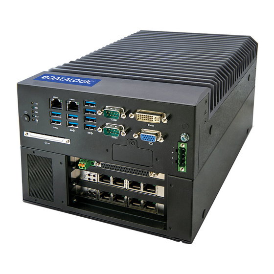
Page 13: Top Panel Connections
MX-E Series Hardware Guide Top Panel Connections Top Panel Connections This illustration shows the connections on the Processor’s top panel. Symbol Function USB 3.0 (x 4) ETH2 - Ethernet 2 (See “Status Lights” on page 10) ETH1 - Ethernet 1 (See “Status Lights” on page 10) RS232 Serial Port (COM 1) - See “Serial Port”... -
Page 14: Front Panel Connections
Front Panel Connections MX-E Series Hardware Guide Front Panel Connections This illustration shows the connections on the Processor’s front panel. Symbol Function Status Lights (see “Status Lights” on page 10) Power Button: Press and release to turn the unit on or off. If the unit is on, press and release to shut down the OS and switch off the unit (see “Turning Off the System”... -
Page 15: Rear View
MX-E Series Hardware Guide Rear View Rear View This illustration shows the Processor’s rear panel. Datalogic S.r.l.. -
Page 16: Status Lights
Status Lights MX-E Series Hardware Guide Status Lights This illustration shows the status lights on the front of the Processor. Symbol Name When lit indicates: Power Power is On Solid-state hard drive or Cfast access is active Link On: An active Smart Display Link connection is estab-... -
Page 17: Preventive Maintenance
This section contains tips to keep your system trouble-free and operating smoothly. • Insure at least 1.5 inches (38.1 mm) of clearance on the sides and top of the MX-E Series Processor. • Periodically check mounting bolts for tightness and wear. The MX-E Series Processor should be mounted securely in a vibration-free location. - Page 18 Before You Call MX-E Series Hardware Guide Datalogic S.r.l.
-
Page 19: Chapter 2: Basic Hardware Components
C H A P T E R Basic Hardware Components Processor Views and Dimensions This section shows specifications for the Processor, including various views and dimensions. Top View Rear View Front View UNITS: mm Datalogic S.r.l. - Page 20 Processor Views and Dimensions MX-E Series Hardware Guide Side View UNITS: mm Air Inlet Filter Inside Datalogic S.r.l.
-
Page 21: Processor Installation
MX-E Series Processors. An optional power supply is available for MX-E Series Processors. If you provide your own, it must supply 24VDC at 5.5 A (nominal) with a safe operating ambient temperature range of 0° to +55° C (+32° to +131° F). - Page 22 Flat Surface Mounting MX-E Series Hardware Guide • Do not exceed the flex radius of any connected cables. Drilling Template Mounting Hole Dimensions UNITS: mm. NOTE: If the Processor uses a Compact Flash card, mount with the Processor top facing upward so the CF card does not fall out due to vibration.
-
Page 23: Power Supply Connection
MX-E Series Hardware Guide Power Supply Connection Power Supply Connection Warning: To avoid electrical shock, disconnect all power to the power supply before working on it. Avertissement: Pour éviter le choc électrique, débranchez toute la puissance à l'alimentation d'énergie avant de tra- vailler à... -
Page 24: Grounding Concepts
Grounding Concepts MX-E Series Hardware Guide Grounding Concepts Functional ground is a low impedance current path between electrical circuits and ground. It is used, for example, to improve immunity to disturbances, but is not a protective measure. Grounding deflects disturbances, but does not neces- sarily provide protection against electric shock. -
Page 25: Usb Hardware Key
MX-E Series Hardware Guide USB Hardware Key USB Hardware Key A USB Hardware key, which contains license and processor configuration information, is ordered and shipped separately from the processor. It must be present in the USB port labeled USB5 on the processor front before the processor is pow- ered on. -
Page 26: Cfast Card
CFast Card MX-E Series Hardware Guide CFast Card A CFast slot is located in the Processor front. A CFast card can be used as removable media for transferring data, perform- ing upgrades, or for extended storage. This CFast slot is connected to the chip set internally via SATA 1 with SATA III design (SATA 6 Gbit/s). -
Page 27: Battery
MX-E Series Hardware Guide Battery Battery WARNING: Risk of explosion if battery is handled improperly or replaced by an incorrect type. Do not recharge, disassemble, or dispose of in fire. Lithium batteries are considered hazardous waste. Dispose of used batteries according to battery maker’s instructions or in accordance with applicable local regulations. - Page 28 Battery MX-E Series Hardware Guide Datalogic S.r.l.
-
Page 29: Chapter 3: M-Series And E-Series Cameras
E-Series cameras have a hard-coat finish case that helps eliminate ground loops. All camera settings (shutter, strobe, par- tial scan, etc.) are configured using Impact software and are maintained in the MX-E Series processors’ memory so there are no physical switches on the cameras. - Page 30 Safety Precautions MX-E Series Hardware Guide NOTE: We recommend that you do not use a switch or a router between the MX-E Series Processor and the camera. • This camera is designed for indoor use. Do not expose it to moisture, including rain or snow, and avoid operating it in wet areas.
-
Page 31: M1Xx And E1Xx Camera Dimensions
MX-E Series Hardware Guide M1xx and E1xx Camera Dimensions M1xx and E1xx Camera Dimensions These cameras weighs approximately 4 ounces (112 grams) with a mounting block, but without a lens. 2 x 1/4-20; 0.31 [8] deep 1.0 [25] 2 x M5 0.31 [8] deep... -
Page 32: M2Xx Camera Dimensions
M2xx Camera Dimensions MX-E Series Hardware Guide M2xx Camera Dimensions The M2xx series of cameras weighs approximately 6.2 ounces (177 grams) with a mounting block, but without a lens. Block Mounting bolts 0.39 [10.0] M3; 4.5mm deep (2 ea.) M5 x 0.8; 8mm deep (2 ea.) -
Page 33: M3Xx Camera Dimensions
MX-E Series Hardware Guide M3xx Camera Dimensions M3xx Camera Dimensions The M3xx series of cameras weighs approximately 8.5 ounces (242 grams) with a mounting block, but without a lens Block Mounting bolts 0.39 [10.0] M3; 4.5mm deep (2 ea.) M5 x 0.8; 8mm deep (2 ea.) -
Page 34: M565/M570/M575/M580 Camera Dimensions
M565/M570/M575/M580 Camera Dimensions MX-E Series Hardware Guide M565/M570/M575/M580 Camera Dimensions The camera weighs approximately 8 ounces (240 grams) without a lens. With an F-mount lens adapter the weight is approximately 11.6 ounces (330 grams). A = I/O Connection B = Power Connection... -
Page 35: M6Xx Camera Dimensions
Rear View Front View Mounting the Camera This section provides instructions for mounting Datalogic cameras. For information about third-party cameras, consult the manufacturer’s documentation for those cameras. To mount an M1xx or E1xx camera 1. With the mounting block held tightly against the camera body, insert the mounting bolts through the mounting bolt holes (see diagram below). - Page 36 Mounting the Camera MX-E Series Hardware Guide 3. Use appropriately sized fasteners in the pre-threaded holes in the bottom of the mounting bracket to secure the mounting block to a rigid surface for proper stability and heat transfer. (See “M1xx and E1xx Camera Dimen- sions”...
- Page 37 MX-E Series Hardware Guide Mounting the Camera To mount an M2xx or M3xx camera 1. With the mounting block held tightly against the camera body, insert two mounting bolts through the mounting bolt holes (see diagram below). 2. Turn the mounting bolt clockwise to tighten the block and secure it to the camera.
-
Page 38: Connecting The Camera
Connecting the Camera MX-E Series Hardware Guide Connecting the Camera WARNING: Never wire M1xx or E1xx Camera Strobe Outputs in parallel with M1xx, E1xx, M2xx, or M3xx Camera Strobe Outputs. This will damage the cameras. M1xx and E1xx Camera Connection To connect M1xx and E1xx camera trigger signals and strobe outputs, use cable 606-0674-xx (6 pin Hirose Male to DB9) with terminal block 661-0399. - Page 39 MX-E Series Hardware Guide M1xx and E1xx Camera Connection M 1 x x a n d E 1 x x C i r c u i t D i a g r a m s M1xx Trigger In Circuit WARNING: Never wire M1xx or E1xx Camera Strobe Outputs in parallel with M1xx, E1xx, M2xx, or M3xx Camera Strobe Outputs.
- Page 40 M1xx and E1xx Camera Connection MX-E Series Hardware Guide M1xx and E1xx Terminal Connections The response times for the strobe output on the M1xx and E1xx camera will typically fall into the ranges specified below. The exact response time for your application will depend on the external resistor and the applied voltage you use.The shutter begins opening simultaneously with the “Camera Strobe Output”...
- Page 41 MX-E Series Hardware Guide M1xx and E1xx Camera Connection microseconds longer than you would on a M2xx to account for the delays. The shutter time must then be set a little longer than the strobe time. Time Delay Rise (TDR) = 40 us Rise Time (RT) = 20 us to 70 us Time Delay Fall (TDF) = 0.6 us...
-
Page 42: M2Xx And M3Xx Camera Connection
M2xx and M3xx Camera Connection MX-E Series Hardware Guide M2xx and M3xx Camera Connection To connect M2xx and M3xx camera power, trigger signals, and strobe outputs, use cable 606- 0673-xx (12-pin Hirose Male to HD-15) with terminal block 661-0400. Terminal... - Page 43 MX-E Series Hardware Guide M2xx and M3xx Camera Connection M 2 x x a n d M 3 x x C i r c u i t D i a g r a m s M2xx and M3xx Trigger In Circuit...
- Page 44 M2xx and M3xx Camera Connection MX-E Series Hardware Guide M2xx and M3xx Terminal Connections Datalogic S.r.l.
-
Page 45: M565/M570/M575/M580 Camera Connection
MX-E Series Hardware Guide M565/M570/M575/M580 Camera Connection The response times for the strobe output on the M2xx and M3xx cameras will typically fall into the ranges specified below. The exact response time for your application will depend on the external resistor and the applied voltage you use. - Page 46 M565/M570/M575/M580 Camera Connection MX-E Series Hardware Guide Terminal Signal Name Notes Input 2 + Single Line Trigger As sinking input Off 0 to +0.8 VDC Phase A Line Trigger On: +2.0 to +5 VDC (Quadrature Encoder) As sourcing input (see Input 2 Pullup) Off: +2.0 to +5 VDC...
- Page 47 MX-E Series Hardware Guide M565/M570/M575/M580 Camera Connection M 5 6 5 / M 5 7 0 / M 5 7 5 / M 5 8 0 C i r c u i t D i a g r a m s...
- Page 48 M565/M570/M575/M580 Camera Connection MX-E Series Hardware Guide Quadrature Encoder Line Trigger Input Circuit 661-0401 Terminal Block Dimensions Datalogic S.r.l.
- Page 49 MX-E Series Hardware Guide M565/M570/M575/M580 Camera Connection Te r m i n a l C o n n e c t i o n s U n t e r m i n a t e d C a b l e C o n n e c t i o n s...
-
Page 50: M6Xx Camera Connection
M6xx Camera Connection MX-E Series Hardware Guide M6xx Camera Connection To connect M6xx camera trigger signals and strobe outputs, use cable 606-0674-xx (6 pin Hirose Male to DB9) with terminal block 661-0399. Terminal Name Signal Notes Optional Camera DO NOT USE... - Page 51 MX-E Series Hardware Guide M6xx Camera Connection M 6 x x C i r c u i t D i a g r a m s M6xx Trigger In Circuit WARNING: Never wire M6xx Camera Strobe Outputs in parallel with M1xx, M2xx, or M3xx Camera Strobe Outputs.
-
Page 52: Third-Party Cameras
M6xx Terminal Connections Third-party Cameras The MX-E Series Processor and Impact Software support only the third-party cameras listed in this section. This informa- tion, including power and trigger signal connections, are provided by us as a convenience. You must purchase a license from us to connect a third-party camera to the M-Series processor. -
Page 53: Jai Cameras
MX-E Series Hardware Guide JAI Cameras JAI Cameras NOTE: See “JAI Camera I/O Signals” on page 54 for important information about camera and strobe signals. Model Resolution Color Image Image Vertical Minimum Software Ver- (GigE) (Megapixels) Horizontal sion Required AT-200GE*... - Page 54 JAI Cameras MX-E Series Hardware Guide Terminal Signal Name Notes Trigger Input + Camera Trigger + +0 to +24 VDC Off: 0 to +2.0 VDC On: +4.0 to + 24 VDC Maximum: +24 VDC Input 2 - Not Currently Supported...
- Page 55 MX-E Series Hardware Guide JAI Cameras JAI Camera Strobe Output Circuit (sinking) JAI Camera Strobe Output Circuit (sourcing) JAI Camera Strobe Output Circuits Sourcing Sinking Datalogic S.r.l.
- Page 56 JAI Cameras MX-E Series Hardware Guide 661-0402 Terminal Block Dimensions Datalogic S.r.l.
- Page 57 MX-E Series Hardware Guide JAI Cameras J A I Te r m i n a l C o n n e c t i o n s JAI Terminal Connections (sourcing) Datalogic S.r.l.
- Page 58 JAI Cameras MX-E Series Hardware Guide JAI Terminal Connections (sinking) Datalogic S.r.l.
- Page 59 MX-E Series Hardware Guide JAI Cameras J A I U n t e r m i n a t e d C a b l e C o n n e c t i o n s JAI Camera Unterminated Cable Connections...
- Page 60 JAI Cameras MX-E Series Hardware Guide 6. In the Devices window, select the camera to be calibrated. 7. Switch to the Feature window. 8. Set the Transport Layer/Read Timeout and the Write Timeout to 3000. 9. Set the User Set Selector to Default and click the User Set Load button.
-
Page 61: Basler Cameras
Basler Cameras The MX-E Series Processor and Impact Software can support a wide variety of Basler GigE cameras, in addition to the models listed below, including all Ace and Scout models. Ace model numbers begin with “acA” and Scout model num- bers begin with “scA.”... - Page 62 Basler Cameras MX-E Series Hardware Guide Terminal Signal Name Notes Trigger In Camera Trigger In (see Note 0 to +24 VDC recommended 1 below) Maximum +30 VDC As sinking input Off: 0 to +1.4 VDC On: +2.2 to +24 VDC; 5 to 15 ma As sourcing input (see Trigger Pullup +VCC) Off: +2.2 to +24 VDC;...
- Page 63 MX-E Series Hardware Guide Basler Cameras C i r c u i t D i a g r a m s Trigger In Circuit Strobe Trigger Out Circuit Datalogic S.r.l.
- Page 64 Basler Cameras MX-E Series Hardware Guide Terminal Connections Datalogic S.r.l.
- Page 65 MX-E Series Hardware Guide Basler Cameras Av i a t o r U n t e r m i n a t e d C a b l e C o n n e c t i o n s Unterminated Cable Connections Datalogic S.r.l.
-
Page 66: Basler Line Scan Camera
Basler Line Scan Camera MX-E Series Hardware Guide Basler Line Scan Camera Model Sensor Size Color Maximum Line Pixel Size Maximum Minimum Software (GigE) Rate Frame Version Required Height ruL2098-10gc 2098 pixels 9.2 kHz 14 x 14 μm 1988 pixels 11.5.0... - Page 67 MX-E Series Hardware Guide Basler Line Scan Camera Connection Terminal Signal Name Notes Input 3 + Phase B Line Trigger As sinking input (Quadrature Encoder) Off 0 to +0.8 VDC On: +2.0 to +5 VDC As sourcing input (see Input 3 Pullup) Off: +2.0 to +5 VDC...
- Page 68 Basler Line Scan Camera Connection MX-E Series Hardware Guide B a s l e r M o d e l r u L 2 0 9 8 - 1 0 g c / r a L 8 1 9 2 - 1 2 g m L i n e...
- Page 69 MX-E Series Hardware Guide Basler Line Scan Camera Connection Quadrature Encoder Line Trigger Input Circuit 661-0401 Terminal Block Dimensions Datalogic S.r.l.
- Page 70 Basler Line Scan Camera Connection MX-E Series Hardware Guide Te r m i n a l C o n n e c t i o n s U n t e r m i n a t e d C a b l e C o n n e c t i o n s...
-
Page 71: Baumer Cameras
MX-E Series Hardware Guide Baumer Cameras Baumer Cameras Model numbers that include a “C” are color cameras. Model Resolution Image Image Vertical Minimum Software (GigE) (Megapixels) Horizontal (approx) Version Required TXG02 - TXG02c 11.5.0 TXG03 - TXG03c 656/656 494/490 11.5.0... -
Page 72: Smartek Cameras
Smartek Cameras MX-E Series Hardware Guide Smartek Cameras Model Resolution Color Image Image Vertical Minimum Software (GigE) Horizontal (Approx) Version Required GC651M 11.2.0 GC652M 11.2.0 GC653M 11.2.0 GC781M 11.2.0 GC1021M 1024 1024 11.2.1 GC1031M 1034 11.2.0 GC1291M 1296 11.2.0 GC1391M... - Page 73 MX-E Series Hardware Guide Smartek Cameras Terminal Color Signal Name Notes Wht/Gry DO NOT USE Gry/Wht DO NOT USE Blu/Wht DO NOT USE Org/Wht DO NOT USE Grn/Wht DO NOT USE Red/Blu Camera Trigger + +0 to +24 VDC Off: 0 to + 1.4 VDC On: +2.2 to + 24 VDC...
- Page 74 Smartek Cameras MX-E Series Hardware Guide Smartek Camera Strobe Output Circuits Sourcing Sinking S m a r t e k Te r m i n a l C o n n e c t i o n s Smartek Terminal Connections (sourcing)
- Page 75 MX-E Series Hardware Guide Smartek Cameras S m a r t e k U n t e r m i n a t e d C a b l e C o n n e c t i o n s...
-
Page 76: Svs-Vistek Cameras (Non-Ip67 Rated)
SVS-Vistek Cameras (non-IP67 rated) MX-E Series Hardware Guide SVS-Vistek Cameras (non-IP67 rated) The following SVS-Vistek camera models are supported: • eco and eco2 series All monochrome models All color models up to five Mpixel • evo and hr series All Monochrome models up to 16 Mpixel (NOT the 29 Mpixel camera) All color models up to 5 Mpixel Dual Ethernet connection NOT SUPPORTED. - Page 77 MX-E Series Hardware Guide SVS-Vistek Cameras (non-IP67 rated) eco655MVGE 2456 2048 10.4.0 eco655CVGE 10.5.0 eco814MT 3360 2712 11.2.1 eco694MT 2752 2204 11.2.1 S V S - V i s t e k ( n o n - I P 6 7 ) C a m e r a C o n n e c t i o n This camera uses two cables, one for Ethernet and one for power and trigger signals.
- Page 78 SVS-Vistek Cameras (non-IP67 rated) MX-E Series Hardware Guide SVS-Vistek Non-IP67 Terminal Connections Datalogic S.r.l.
-
Page 79: Svs-Vistek Cameras (Ip67 Rated)
MX-E Series Hardware Guide SVS-Vistek Cameras (IP67 rated) SVS-Vistek Cameras (IP67 rated) Model Resolution Color Image Image Vertical Minimum Software (GigE - IP67) (Megapixels) Horizontal (approx) Version Required eco204MVGE67 <1 1024 10.4.0 eco204CVGE67 10.5.0 eco267MVGE67 1360 1024 10.4.0 eco267CVGE67 10.5.0... - Page 80 SVS-Vistek Cameras (IP67 rated) MX-E Series Hardware Guide SVS-Vistek I/O Circuit SVS-Vistek Terminal Connections Datalogic S.r.l.
-
Page 81: Camera Specifications
MX-E Series Hardware Guide Camera Specifications Camera Specifications E-Series E1xx, E1xxC All E1xx cameras have the following specifications. Model numbers that end in “C” are color cameras. E1xx Common Specifications Lens Mount C mount Cabling Camera cable provides trigger. Ethernet cable transmits video and provides POE. -
Page 82: E151, E151C
E151, E151C MX-E Series Hardware Guide E101 Specifications Capture Rate 300 full-resolution fps; higher with partial scan Pixel Size 4.8 x 4.8 micrometers Gain 100% to 1023% Shutter Open 112 to 1,000,000 microseconds Software Version Impact Software Release 11.8.0.97 or greater E151, E151C This camera captures a 1280 x 1024 pixel size image with square pixels. -
Page 83: E181, E181C
MX-E Series Hardware Guide E181, E181C E181, E181C This camera captures a 1920 x 1200 pixel size image with square pixels. It can partially scan the image horizontally and vertically. E181 Spectral Response (excludes lens and light source characteristics) E181 Specifications... -
Page 84: E182, E182C
E182, E182C MX-E Series Hardware Guide E182, E182C This camera captures a 1600 x 1200 pixel size image with square pixels. It can partially scan the image horizontally and vertically. E182 Spectral Response (excludes lens and light source characteristics) E182 Specifications Part Number 959933038;... -
Page 85: E193, E193C
MX-E Series Hardware Guide E193, E193C E193, E193C This camera captures a 2048 x 1536 pixel size image with square pixels. It can partially scan the image horizontally and vertically. E193 Spectral Response (excludes lens and light source characteristics) E193 Specifications Part Number 959933042;... -
Page 86: E198, E198C
E198, E198C MX-E Series Hardware Guide E198, E198C This camera captures a 2448 x 2048 pixel size image with square pixels. It can partially scan the image horizontally and vertically. E198C Spectral Response (excludes lens and light source characteristics) E198 Specifications Part Number 959933044;... -
Page 87: M-Series
MX-E Series Hardware Guide M-Series M-Series M1xx, M1xxC All M1xx cameras have the following specifications. Model numbers that end in “C” are color cameras. M1xx Common Specifications Lens Mount C mount Cabling Camera cable provides trigger. Ethernet cable transmits video and provides POE. -
Page 88: M150, M150C
M150, M150C MX-E Series Hardware Guide M110 Specifications Shutter Open 24 to 1,000,000 microseconds Exposure Start Delay 31.72 μsec Software Version Impact Software Release10.3.0 or greater M150, M150C This camera captures a 1296 by 966 pixel size image with square pixels. It can partially scan the image horizontally and vertically. -
Page 89: M180, M180C
MX-E Series Hardware Guide M180, M180C M180, M180C This camera captures a 1628 by 1236 pixel size image with square pixels. It can partially scan the image horizontally and vertically. M180 Spectral Response (excludes lens and light source characteristics) M180 Specifications Part Number 601-0357;... -
Page 90: M190, M190C
M190, M190C MX-E Series Hardware Guide M190, M190C This camera captures a 2048 by 1088 pixel size image with square pixels. It can partially scan the image horizontally and vertically. M190 Spectral Response (excludes lens and light source characteristics) M190 Specifications Part Number 601-0454;... -
Page 91: M195, M195C
MX-E Series Hardware Guide M195, M195C M195, M195C This camera captures a 2048 by 2048 pixel size image with square pixels. It can partially scan the image horizontally and vertically. M195 Spectral Response (excludes lens and light source characteristics) M195 Specifications Part Number 601-0456;... -
Page 92: M197, M197C
M197, M197C MX-E Series Hardware Guide M197, M197C This camera captures a 2592 by 1944 pixel size image with square pixels. M197 Spectral Response (excludes lens and light source characteristics) M197 Specifications Pick-up Device Progressive Scan CMOS, Rolling Shutter - 2592(H) x 1944 (V) pixels Sensor Size 1/2.5”... -
Page 93: M2Xx, M2Xx-Ra, M2Xxc, M2Xxc-Ra
MX-E Series Hardware Guide M2xx, M2xx-RA, M2xxC, M2xxC-RA M2xx, M2xx-RA, M2xxC, M2xxC-RA All M2xx, M2xx-RA, M2xxC, and M2xxC-RA cameras have the following specifications. Model numbers that include a “C” are color cameras. Model numbers that end in “-RA” are right-angle mount cameras. -
Page 94: M210 Line
M210 line MX-E Series Hardware Guide M205 Specifications Power 24 VDC provided by camera cable (3 Watts) Software Version Impact Software Release 10.0.0 or greater M210 line This camera line captures a 782 by 582 pixel size image with square pixels. It can partially scan the image horizontally and vertically. -
Page 95: M230 Line
MX-E Series Hardware Guide M230 line M230 line This camera line captures a 1034 by 779 pixel size image with square pixels. It can partially scan the image horizontally and vertically. M230 Spectral Response (excludes lens and light source characteristics) -
Page 96: M270 Line
M270 line MX-E Series Hardware Guide M270 line This camera line captures a 1392 by 1040 pixel size image with square pixels. It can partially scan the image horizontally and vertically. M270 Spectral Response (excludes lens and light source characteristics) -
Page 97: M290 Line
MX-E Series Hardware Guide M290 line M290 line This camera line captures a 1628 by 1236 pixel size image with square pixels. It can partially scan the image horizontally and vertically. M290 Spectral Response (excludes lens and light source characteristics) -
Page 98: M565/M570/M575/M580 Camera
M565/M570/M575/M580 Camera MX-E Series Hardware Guide M565/M570/M575/M580 Camera These cameras have the following specifications. Spectral Response (excludes lens and light source characteristics) M565/M570/M575/M580 Common Specifications Lens Mount F or C mount; Add -F to part number for F mount Cabling 6-pin cable provides power. -
Page 99: M570 Camera
MX-E Series Hardware Guide M570 camera M570 camera This camera captures a 4096 pixel width image with a maximum line rate of 26khz.It is a monochrome, GigE line scan camera with the following specifications. M570 Specifications Sensor Size 4096 pixels... -
Page 100: M6Xx, M6Xxc
M6xx, M6xxC MX-E Series Hardware Guide M6xx, M6xxC All M6xx and M6xxC cameras have the following specifications. Model numbers that include a “C” are color cameras. M6xx Common Specifications Lens Mount C mount Cabling Camera cable provides trigger. Ethernet cable transmits video and provides POE. -
Page 101: M610 And M610C
MX-E Series Hardware Guide M610 and M610C M610 and M610C This camera line captures a 640 by 480 pixel size image with square pixels. It can partially scan the image horizontally and vertically. M610 Spectral Response (excludes lens and light source characteristics) -
Page 102: M650 And M650C
M650 and M650C MX-E Series Hardware Guide M610 and M610C Specifications Software Version Impact Software Release 11.7.0 or greater M650 and M650C This camera captures a 1280 by 960 pixel size image with square pixels. It can partially scan the image horizontally and vertically. -
Page 103: M680 And M680C
MX-E Series Hardware Guide M680 and M680C M650 and M650C Specifications Pixel Size 3.75 x 3.75 micrometers Gain 0% to 18% Shutter Open 30 to 1,000,000 microseconds Software Version Impact Software Release 11.7.0 or greater M680 and M680C This camera captures a 1600 by 1200 pixel size image with square pixels. It can partially scan the image horizontally and vertically. - Page 104 M680 and M680C MX-E Series Hardware Guide M680 and M680C Specifications Pick-up Device Global Shutter CCD - 1688 (H) x 1248 (V) pixels Sensor Size 1/1.8” (8.99 mm) diag - 7.16 mm (H) x 5.44 mm (V) Capture Rate 20 full-resolution fps; higher with partial scan Pixel Size 4.40 x 4.40 micrometers...
-
Page 105: Chapter 4: Processor I/O
Processor I/O Connection To connect MX-E Series processor input and output signals use either cable 606-0675-xx (37 pin D-sub Male to Male Cable) with terminal block 248-0110 or remove one end (to create pigtail) with no terminal block. Use shielded cable for all connections. - Page 106 Processor I/O Connection MX-E Series Hardware Guide Connector or terminal Color Code Signal Name number Red/White Input 14- Orange/White Input 15- Green/White Input 16- Blue/White Input Plus (Note 2) Purple/White No Connection Red/Black Output Minus (Note 1) Orange/Black Output 1...
- Page 107 MX-E Series Hardware Guide Processor I/O Connection Connector or terminal Color Code Signal Name number Yellow Input 4- Green Input 5- Blue Input 6- Purple Input 7- Gray Input 8- White Input 9- Pink Input 10- Light Green Input 11-...
-
Page 108: Processor Inputs
MX-E Series Hardware Guide Processor Inputs The MX-E Series Processors contain sixteen general-purpose input connections. Two inputs serve as both event and polled inputs (Inputs 1 and 2). The remaining inputs are polled. The event inputs are interrupt-driven which means that a change of state on the input will immediately cause an action and any inspection task that uses that input will be queued to run. - Page 109 MX-E Series Hardware Guide Input Wiring Current Sourcing (PNP) Input Circuit The diagram below shows how to wire a sensor to a general purpose or event input for model numbers containing the let- ter “P.” All inputs are compatible with current sourcing output signals. Pin 1 is the “Input Minus Common” connection for all the inputs.
-
Page 110: Processor Outputs
Processor Outputs MX-E Series Hardware Guide Processor Outputs The MX-E Series Processors contain sixteen general-purpose output connections. The table below describes the output’s electrical characteristics. Supply Voltage +12 to +24 VDC (±10%) Maximum Output +35 VDC Output Current 100 Milliamperes per channel (maximum) Note: An external power source is required to power an output load. -
Page 111: Output Wiring
MX-E Series Hardware Guide Output Wiring Output Wiring Current Sinking (NPN) Output Circuit The diagrams below show internal circuit diagrams and how to wire processor outputs for model numbers containing the letter “N.” This is an internal connection, not an output voltage source. An exter-... - Page 112 Output Wiring MX-E Series Hardware Guide Current Sourcing (PNP) Output Circuit The diagrams below show internal circuit diagrams and how to wire processor outputs for model numbers containing the letter “P.” This is an internal connection, not an output voltage source. An exter- nal power source must be con- nected to the Load, as indicated.
-
Page 113: Chapter 5: Cable Reference
Ethernet An Ethernet cable (Part number 606-0677-xx) is used to connect the MX-E Series Processor to the GigE camera and between the Processor and any external network. The last two digits of the part number indicate the cable length in feet. -
Page 114: Serial Port
Serial Port MX-E Series Hardware Guide Serial Port A standard serial cable is used to connect the Processor to the serial port on an external device (e.g. terminal, PLC, motion controller, data recorder). This may require using a null modem cable or adapter. The serial port does not support hard- ware (CTS/RTS) or software (Xon/Xoff) data flow control. -
Page 115: Camera Cable
MX-E Series Hardware Guide Camera Cable Camera Cable M1xx and E1xx The terminal block and cable for connecting M1xx and E1xx cameras are listed in the table below. For cable wire color codes and connection diagrams, see “M1xx and E1xx Camera Connection” on page 32. The last two digits of the part number indicate the cable length in meters. - Page 116 M1xx and E1xx MX-E Series Hardware Guide Datalogic S.r.l.
- Page 117 M5xx Front connector mounting M6xx Smartek SVS-Vistek Hardware components third-party Hardware key Cfast Circuit M2xx M3xx Color shading cable Compact flash reference Connector Input/Output DisplayPort See I/O DVI-I Inputs ethernet processor front Installation power processor Interrupts Datalogic S.r.l.
- Page 118 Index MX-E Series Hardware Guide specifications wiring Maintenance camera Monitor/panel color shading cable Mounting wiring processor, flat Mounting camera M1xx, M2xx, M3xx, E1xx M5xx M6xx USB Hardware Outputs Lights processor status M110, M110C status M150, M150C Port M180, M180C serial...
- Page 119 MX-E Series Hardware Guide Index Specifications Turn off system E1xx, E1xxC M1xx, M1xxC M2xx, M2xxC USB connector M565/M570/M575/M580 USB Hardware key M6xx, M6xxC processor Status lights Support, technical VGA connector SVS-Vistek camera wiring Weight Switch M1xx, E1xx power M2xx System shut down...
- Page 120 Index MX-E Series Hardware Guide Datalogic S.r.l.
Need help?
Do you have a question about the MX-E Series and is the answer not in the manual?
Questions and answers