Advertisement
Quick Links
IMPORTANT
Read this entire installation manual to
ensure proper installation.
Make sure that water supply is completely
off before beginning installation.
The Tri-Fount™ requires a water flowing
pressure of at least 20 psi but no greater
than 80 psi.
Flush all the water supply lines before
making connections.
Wall anchors used must have a minimum
pull-out rating of 1,000 lbs.
File these instructions with the owner or
maintenance department.
215-1372 Rev. F; EN 03-045
© 2003 Bradley Corporation
Page 1 of 16
9-17-2003
Installation
Instructions
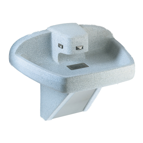
Bradley Multi-Fount™ Series
MF2939/BIR
®
Terreon
Tri-Fount
Hung Washfountain with
Battery Operated Infrared
Control
(Standard* & Juvenile
Height)
*ADA compliant when mounted at recommended
heights
Table of Contents
Pre-Installation Information . . . . . . . . . . . . .2-3
Installation Instructions . . . . . . . . . . . . . . . .4-12
Activation Range Adjustment . . . . . . . . . . . . .11
Cleaning and Maintenance . . . . . . . . . . . .13-14
Valve Box Troubleshooting . . . . . . . . . . . . . .15
Battery Troubleshooting . . . . . . . . . . . . . . . . .16
Flow Restrictions . . . . . . . . . . . . . . . . . . . . . .16
P.O. Box 309, Menomonee Falls, WI 53052-0309
TEL. 1-800-BRADLEY
http://www.bradleycorp.com
TM
Wall-
FAX 262-251-5817
Advertisement

Related Manuals for Bradley Terreon Tri-Fount Multi-Fount Series


Summary of Contents for Bradley Terreon Tri-Fount Multi-Fount Series
-
Page 1: Table Of Contents
1,000 lbs. File these instructions with the owner or maintenance department. P.O. Box 309, Menomonee Falls, WI 53052-0309 TEL. 1-800-BRADLEY FAX 262-251-5817 215-1372 Rev. F; EN 03-045 http://www.bradleycorp.com © 2003 Bradley Corporation Page 1 of 16 9-17-2003... -
Page 2: Pre-Installation Information
1. This warranty is limited to replacing or repairing, at our option, transportation charges prepaid by the purchaser, any Bradley unit or part thereof which our inspection shall show to have been defective within the limitations of this warranty. -
Page 3: Rev. F; En
Separate all parts from packaging materials and ensure you have all the parts required for assembly. If any parts are missing, do not attempt to assemble the Wall-Hung Tri-Fount™ until you obtain all parts. Bradley Corporation • 215-1372 Rev. F; EN 03-045 9-17-2003... -
Page 4: Installation Instructions
(108) 27-1/2"* 28"* 26-1/2"* (699) (711) (660) 25-1/2"* 23-1/4"* (648) (591) 10" 18-3/4"* (476) (254) FINISHED FLOOR FINISHED FLOOR Figure 1 * Subtract 4" from this dimension for juvenile height model. 9-17-2003 Bradley Corporation • 215-1372 Rev. F; EN 03-045... - Page 5 Connect the 90° elbow to the 1/2" tempered supply line as shown in Figure 2a. Optional Single Tempered Supply Braided Hoses From Valve Box Check/Stop 90° Elbow To Supply Line Cross Figure 2a Bradley Corporation • 215-1372 Rev. F; EN 03-045 9-17-2003...
- Page 6 5/16 lockwasher provided. Slide the battery box onto the bracket (see Figure 3). Left Battery valve box pedestal panel Battery Valve Box Bracket Frame 1/4-20 Screw 5/16 Lockwasher Attach Battery Valve Box Right Bracket at this location pedestal panel Figure 3 9-17-2003 Bradley Corporation • 215-1372 Rev. F; EN 03-045...
- Page 7 Back View of Washfountain Bowl Drain Assembly #10-24 x 1/2" Dome Screw for Strainer Strainer Drain Spud Washfountain Bowl Spud Discard this Washer washer; it is not used on Spud washfountains Locknut Figure 4 Bradley Corporation • 215-1372 Rev. F; EN 03-045 9-17-2003...
- Page 8 2. Connect the smaller diameter flexible hose from the Vernatherm™ Valve to the battery boxes. Stop/Check Filter Washer 1/2" Elbow Mounting Stud Nut and Washer Pipe Clamp Vernatherm™ Assembly Pipe Cross Braided Hoses Figure 6 9-17-2003 Bradley Corporation • 215-1372 Rev. F; EN 03-045...
- Page 9 (see Figures 7a and 7b). Connections to the sprayhead sensors and outlet tubes are shown in Figure 7b. Sprayhead #1 Sprayhead #2 Sprayhead #3 S = Sensor—Transmitter or Receiver W = Outlet Tube Valve Box Valve Box Figure 7b Bradley Corporation • 215-1372 Rev. F; EN 03-045 9-17-2003...
- Page 10 1. Remove the four Phillips head screws from the valve box cover (see Figure 8a). 2. Install twelve "AA" alkaline batteries (not included). IMPORTANT: Wait for five seconds before testing the unit (allows sensors to adapt to site conditions). Filter Screen Figure 8a Figure 8b 9-17-2003 Bradley Corporation • 215-1372 Rev. F; EN 03-045...
-
Page 11: Activation Range Adjustment
5. Wait five seconds for the sensor to adapt, then test the range. If the range is okay, then replace the valve box cover and tighten the screws. Bradley Corporation • 215-1372 Rev. F; EN 03-045 9-17-2003... - Page 12 3. Secure the access panel to the top of the pedestal frame using the self-retaining screw. 4. Tighten the screw to secure the bottom of the access panel in place. Pedestal Frame Self Retaining Screw Acess Panel Figure 10 #10-32 x 3/8" Bracket Slot Screw 9-17-2003 Bradley Corporation • 215-1372 Rev. F; EN 03-045...
-
Page 13: Cleaning And Maintenance
® Solid Surface cleaner and polish to refresh and protect the Terreon Solid Surface material.Bradley recommends additional care and maintenance for the darker colored Terreon, for complete instructions on this additional maintenance see Bradley document #1505. IMPORTANT: DO NOT USE STRONG ACID OR ALKALINE CHEMICALS AND CLEANSERS TO CLEAN TERREON. - Page 14 It is emphasized that all products should be used in strict accordance with package instructions. 9-17-2003 Bradley Corporation • 215-1372 Rev. F; EN 03-045...
-
Page 15: Valve Box Troubleshooting
2. Remove the sensor “eyes” from the sprayhead taking care to keep dirt/debris and water out of the sprayhead sensor windows. 3. Pry the valve box up to loosen from the hook-and-loop pad. 4. Replace the valve box and reassemble the valve box in reverse order. Bradley Corporation • 215-1372 Rev. F; EN 03-045 9-17-2003... -
Page 16: Battery Troubleshooting
Water Does not Shut Off Problem: Water continues to flow after sensor is deactivated. Cause: Batteries removed while sensor was activated leaving motor driven valve in the open position. Solution: Reinstall batteries. 9-17-2003 Bradley Corporation • 215-1372 Rev. F; EN 03-045...
Need help?
Do you have a question about the Terreon Tri-Fount Multi-Fount Series and is the answer not in the manual?
Questions and answers