
Subscribe to Our Youtube Channel
Related Manuals for FLIR Raymarine gS Series


Summary of Contents for FLIR Raymarine gS Series
- Page 1 gS SERIES INSTALLATION INSTRUCTIONS English Date: 08-2015 Document number: 87248-2-EN © 2015 Raymarine UK Limited...
- Page 3 Gear Up, Marine Shield, Seahawk, Autohelm, Automagic, and Visionality are registered or claimed trademarks of Raymarine Belgium. FLIR, DownVision, SideVision, Dragonfly, Instalert, Infrared Everywhere, and The World’s Sixth Sense are registered or claimed trademarks of FLIR Systems, Inc. All other trademarks, trade names, or company names referenced herein are used for identification only and are the property of their respective owners.
-
Page 5: Table Of Contents
Contents Chapter 1 Important information......7 4.11 NMEA 0183 connection — Power/NMEA/Video cable................. 41 Certified Installation ............. 7 4.12 Gigabit networking ..........42 Product operation in high temperatures ......7 4.13 Sonar module connection ........43 Power over Ethernet (PoE)........... 8 4.14 Radar network connection ........ - Page 6 9.1 Raymarine product support and servicing ....90 9.2 Learning resources ..........91 9.3 Third-party support..........91 Chapter 10 Spares and accessories ....93 10.1 gS Series accessories ........94 10.2 gS Series spares..........94 10.3 Network hardware ..........95 10.4 Network cable connector types......
-
Page 7: Chapter 1 Important Information
Chapter 1: Important information Warning: FCC Warning (Part 15.21) Changes or modifications to this equipment not expressly approved in Certified Installation writing by Raymarine Incorporated could violate compliance with FCC rules and Raymarine recommends certified installation by a void the user’s authority to operate the Raymarine approved installer. -
Page 8: Power Over Ethernet (Poe)
occurs, you may notice a slight degradation in the Caution: Sun covers performance of the unit, in terms of responsiveness • If your product is supplied with a sun to user operation. cover, to protect against the damaging This is expected behavior, designed to protect the effects of ultraviolet (UV) light, always unit from the adverse effects of excessive heat. -
Page 9: Tft Displays
Raymarine does not warrant that this product is Class 3 / error-free or that it is compatible with products Class 1 (3.84 Class 2 (6.49 Class 0 Total power manufactured by any person or entity other than (12.95 W) used Raymarine. -
Page 10: Industry Canada
Japanese approvals 2. Increase the separation between the equipment and receiver. In the frequency band used for this device, campus radio 3. Connect the equipment into an outlet on a stations (radios stations that require a license) and specified circuit different from that to which the receiver low power radio stations (radio stations that do not require is connected. -
Page 11: Warranty Registration
Warranty registration To register your Raymarine product ownership, please visit www.raymarine.com and register online. It is important that you register your product to receive full warranty benefits. Your unit package includes a bar code label indicating the serial number of the unit. You will need this serial number when registering your product online. - Page 12 gS Series installation instructions...
-
Page 13: Chapter 2 Document And Product Information
Chapter 2: Document and product information Chapter contents • 2.1 Document information on page 14 • 2.2 Product documentation on page 14 • 2.3 Document illustrations on page 15 • 2.4 Product overview on page 15 • 2.5 LightHouse MFD Operation instructions on page 16 Document and product information... -
Page 14: Document Information
2.1 Document information 2.2 Product documentation This document contains important information The following documentation is applicable to your related to the installation of your Raymarine product. product: The document includes information to help you: Documentation • plan your installation and ensure you have all the Description Part number necessary equipment;... -
Page 15: Document Illustrations
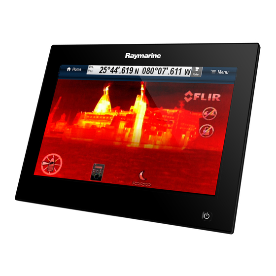
2.3 Document illustrations 2.4 Product overview Products may differ slightly from those shown in the Product information illustrations in this document, depending on product gS Series Multifunction Displays (MFDs) are variant and date of manufacture. touchscreen displays which have HybridTouch The illustration shown below is used throughout functionality when paired with a remote keypad. -
Page 16: Lighthouse Mfd Operation Instructions
2.5 LightHouse MFD Operation instructions For operation instructions for your MFD, including ‘Getting Started’ and ‘System Checks’ information please use the User Manual icon on the Homescreen. the LightHouse Operation Instructions (81360) can also be downloaded from the Raymarine website: www.raymarine.com/manuals gS Series installation instructions... -
Page 17: Chapter 3 Planning The Installation
Chapter 3: Planning the installation Chapter contents • 3.1 System integration on page 18 • 3.2 Installation checklist on page 24 • 3.3 Multiple data sources (MDS) overview on page 24 • 3.4 Identifying your display variant on page 25 •... -
Page 18: System Integration
3.1 System integration Raymarine ® multifunction displays (MFDs) are compatible with a wide range of marine electronics devices. Display T rue/App T ack INTCM AUDIO ANTENNA NETWORK P OWER D13330-1 MFDs use various protocols to transfer data between devices in your system. The table below details which devices may be connected to your MFD, and the type of connections (in terms of protocols and physical interfaces): Item... - Page 19 Item Device Type Maximum quantity Suitable Devices Connections Vessel tank sensors • Up to 5 x fuel. Third-party NMEA 2000 interfaces NMEA 2000 (via optional — third-party DeviceNet adaptor cables) • 1 x fresh water. • 1 x waste water. •...
- Page 20 Item Device Type Maximum quantity Suitable Devices Connections • S2 • S3 AIS — Raymarine ® • AIS350 SeaTalk ng® , or NMEA 0183 • AIS650 • AIS950 AIS — third-party Third-party NMEA NMEA 0183 0183–compatible AIS Class A or Class B receiver / transceiver Vessel trim tabs —...
- Page 21 Item Device Type Maximum quantity Suitable Devices Connections Sonar transducer • P48 Direct connection to 600 W internal sonar variant displays. • P58 • P74 • B60 20º • B60 12º • B744V ; OR: • Any 600 watt / 1Kw compatible transducer (via optional E66066 adaptor cable) ;...
- Page 22 Item Device Type Maximum quantity Suitable Devices Connections Additional 3rd generation Raymarine ® SeaTalk multifunction multifunction displays display(s) — SeaTalk (recommended): Raymarine ® • a Series • c Series • e Series • gS Series • eS Series Note: You can connect Raymarine ®...
- Page 23 Item Device Type Maximum quantity Suitable Devices Connections Fusion entertainment Multiple Fusion 700 series entertainment SeaTalk systems systems: • MS-IP700 • MS-AV700 PC / laptop Windows-compatible PC or laptop SeaTalk running Raymarine ® Voyage Planner software. Note: Raymarine ® cannot guarantee the compatibility of any third-party devices listed above. Planning the installation...
-
Page 24: Installation Checklist
3.2 Installation checklist 3.3 Multiple data sources (MDS) overview Installation includes the following activities: Installations that include multiple instances of data Installation Task sources can cause data conflicts. An example is an Plan your system. installation featuring more than one source of GPS data. -
Page 25: Identifying Your Display Variant
3.4 Identifying your display variant 3.5 Networking constraints To discover which model display you have follow the Up to 10 LightHouse powered MFDs can steps below: be connected together using SeaTalk . It is recommended that all networked displays contain the same software version. -
Page 26: System Protocols
3.6 System protocols Note: • All MFDs must have LightHouse II Release Your Multifunction Display can connect to various V10.41 software or later to enable multiple sonar instruments and displays to share information and support. so improve the functionality of the system. These connections may be made using a number of •... -
Page 27: Data Master
3.7 Data master a whole network of marine electronics from any manufacturer to communicate on a common bus via Any system containing more than one networked standardized message types and formats. multifunction display must have a designated data master. SeaTalk The data master is the display which serves as a SeaTalk is a protocol which enables compatible primary source of data for all displays, it also handles... -
Page 28: Parts Supplied
3.8 Parts supplied HD-SDI additional parts supplied The gS195 is supplied with the following additional The following parts are supplied with your product. parts for use with the HD-SDI connection. D13051-2 Protective boot 75 ohm BNC connector Cable ties x 2 (to secure the protective boot) D12886-2 Multifunction display 2 x Display mounting brackets... -
Page 29: Tools Required For Installation
3.9 Tools required for installation 3.10 Selecting a location Warning: Potential ignition source This product is NOT approved for use in hazardous/flammable atmospheres. Do NOT install in a hazardous/flammable atmosphere (such as in an engine room or near fuel tanks). General location requirements When selecting a location for your product it is important to consider a number of factors. - Page 30 Compass safe distance Caution: Mounting surface requirements To prevent potential interference with the vessel's magnetic compasses, ensure an adequate distance This product is heavy. To prevent potential is maintained from the display. damage to the product and / or your vessel, observe the following BEFORE When choosing a suitable location for the installing the product:...
- Page 31 Viewing angle considerations Vessel construction The construction of your vessel can have an impact As display contrast, color and night mode on GPS performance. For example, the proximity performance are all affected by the viewing angle, of heavy structure such as a structural bulkhead, Raymarine recommends you temporarily power up or the interior of larger vessels may result in a the display when planning the installation, to enable...
-
Page 32: Product Dimensions
orientation orientation gS165 12 O’clock gS165 INV 6 O’clock (E70126) (E70185) gS195 6 O’clock (E70213) Product dimensions D12716-2 gS95 gS125 gS165 gS195 246.8 mm 311.8 mm 383.2 mm 433.9 mm (9.7 in) (12.3 in) (15 in) (17.1 in) 188.2 mm 237.1 mm 284.7 mm 391.2 mm... -
Page 33: Chapter 4 Cables And Connections
Chapter 4: Cables and connections Chapter contents • 4.1 General cabling guidance on page 34 • 4.2 gS95 / gS125 / gS165 Connections overview on page 35 • 4.3 gS195 connections overview on page 35 • 4.4 Power and data (combined) connection on page 36 •... -
Page 34: General Cabling Guidance
4.1 General cabling guidance Always route data cables as far away as possible from: Suppression ferrites • other equipment and cables, • Raymarine cables may be pre-fitted or supplied • high current carrying ac and dc power lines, with suppression ferrites. These are important for correct EMC performance. -
Page 35: Gs95 / Gs125 / Gs165 Connections Overview
4.2 gS95 / gS125 / gS165 Connections 4.3 gS195 connections overview overview Details of the connections available on the gS195 are shown below. Details of the connections available on the multifunction display are shown below. D13044-3 D12700-1 SeaTalk connection SeaTalk HDMI Output HDMI PoE / RayNet SeaTalk... -
Page 36: Power And Data (Combined) Connection
4.4 Power and data (combined) NOT use a power cable designed for, or supplied with, a different product. connection • Refer to the Power connection section for more The details below apply to MFDs that have a information on how to identify the wires in your combined power/NMEA/video cable. - Page 37 • ABYC TE-4 Lightning Protection Battery connection scenario A: suitable for a vessel with a common RF ground point. In this scenario, if your Power cable extension product’s power cable is supplied with a separate drain wire then it should be connected to the vessel’s common The product is supplied with a power cable, which ground point.
-
Page 38: Power Over Ethernet (Poe)
4.5 Power over Ethernet (PoE) 4.6 Card reader connection This product can supply Power over Ethernet (PoE) The card reader must be connected directly to the to class 1, 2 and 3 devices. The product can output dedicated card reader connector on the rear of the a maximum of 20 Watts for consumption by PoE display. -
Page 39: Auxiliary Alarm Connection
4.7 Auxiliary alarm connection 4.8 SeaTalk ng® connections The MFD can connect to a SeaTalk ng® backbone. The auxiliary alarm can be connected to the Video in / Alarm out connector of the multifunction display. SeaTalk ng® can be used to communicate with: Refer to the Connections overview section to •... -
Page 40: Nmea 2000 Connection
4.9 NMEA 2000 connection • Other suitable 12 V power supply. Note: SeaTalk does NOT supply power to The display can receive data from NMEA 2000 multifunction displays and other equipment with a devices (e.g. data from compatible engines). The dedicated power supply input. -
Page 41: Seatalk Connection
4.10 SeaTalk connection 4.11 NMEA 0183 connection — Power/NMEA/Video cable You can connect SeaTalk devices to your MFD using the optional SeaTalk to SeaTalk ng® converter. NMEA 0183 devices can be connected directly to MFDs with a combined Power/NMEAVideo cable. Refer to the Connection Overview section to establish the NMEA 0183 connection method for your MFD. -
Page 42: Gigabit Networking
4.12 Gigabit networking Posi- tive (+) It is recommended that MFDs with gigabit (1000 Ite- Cable Input / / nega- Mbits/s) network ports are daisy-chained together. Device color Port output tive (-) One of the MFDs should then be connected to the Orange / Input Positive... -
Page 43: Sonar Module Connection
4.13 Sonar module connection This does NOT apply to any systems that do NOT include a CP300 or CP450C sonar module. External sonar modules can be connected directly to Note: For software downloads and instructions the display’s network connection or can be connected on how to update the software for your product(s), to the SeaTalk network, via a Raymarine... -
Page 44: Radar Network Connection
4.14 Radar network connection 2. MFD 3. Network connection to MFD (RayNet Radar Radar units are connected to the SeaTalk network, cable) usually via a Raymarine ® network switch. On smaller systems the Radar may be connected 4. Power connection directly to the display’s network connection. - Page 45 Radar cable extension For longer cable runs a Radar power and data digital cable extension is required. D12254-1 1. Radar extension cable. 2. Radar power and data digital cable. 3. Raymarine ® network switch (or crossover coupler if connecting Radar directly to display). 4.
-
Page 46: Gnss / Gps Connection
4.15 GNSS / GPS connection Radar power and data digital extension cables Depending on display variant, your multifunction These cables extend the power and data digital display may include an internal GNSS or GPS cables for a scanner's power and data connections. receiver. -
Page 47: Ais Connection
4.16 AIS connection 4.17 Fastheading connection A compatible AIS unit can be connected using If you wish to use MARPA (radar target acquisition) SeaTalk ng® or NMEA 0183. functions on your multifunction display you need either: Connection using SeaTalk ng® •... -
Page 48: Keypad Network Connection
4.18 Keypad network connection 4.19 Weather receiver connection Raymarine ® remote keypads (e.g. the RMK-9) A Sirius XM weather receiver can be connected can be connected directly to the display’s network directly to the display’s network connection or can connection or can be connected to the SeaTalk be connected to the SeaTalk network, via a network, via a Raymarine... -
Page 49: Video Connection - Composite
4.20 Video connection — composite 4.21 Camera (Video/Alarm) connection Analog cameras can be connected directly to MFDs A camera or a video device can be connected that have a composite video input connection. directly your MFD using the dedicated Video / alarm connector. -
Page 50: Hdmi Video Output
4.22 HDMI video output 4.23 IP Camera connection Raymarine ® IP cameras can be connected If your MFD has a HDMI output connection the directly to the display’s network connection or can MFD’s screen can be output to an external display. be connected to the SeaTalk network, via a Refer to the Connection Overview section to... -
Page 51: Hd-Sdi Connection (Gs195)
4.24 HD-SDI connection (gS195) For further information regarding camera installation (including power connection and mounting), refer to The gS195 includes a High Definition Serial Digital the installation instructions supplied with the camera. Interface (HD-SDI), which can be used to view a compatible video source using the multifunction IP camera guidance display’s Camera application. -
Page 52: Thermal Camera Connection
4.25 Thermal camera connection Connecting the data cable Follow the steps below to connect your HD-SDI data Thermal cameras can be connected directly to the cable to the multifunction display. display’s network connection or can be connected to the SeaTalk network, via a Raymarine ®... - Page 53 4. Raymarine ® network switch Raymarine recommends the use of a BNC terminated RG59 75ohm (or better) coaxial cable. 5. Video cable 6. RayNet to RJ45 SeaTalk adaptor cables 7. PoE (Power over Ethernet) injector (only required if using the optional JCU) 8.
-
Page 54: Fusion Network Connection
4.26 Fusion network connection 4.27 Fusion NMEA 2000 connection Fusion 700 and 750 Series marine entertainment Compatible Fusion NMEA 2000 marine systems can be connected directly to the display’s entertainment systems can be connected to the network connection or can be connected to the SeaTalk ng®... -
Page 55: Media Player Connection
4.28 Media player connection 4.29 Raymarine mobile app connection You can use your MFD to control a Bluetooth media You can use compatible tablet and smartphone player (such as a smartphone). devices as a wireless repeat display or remote control for your multifunction display. The media player must be compatible with the Bluetooth 2.1+ EDR power class 1.5 (supported Raymarine apps allow you to stream and / or control,... -
Page 56: Bluetooth Remote Control Connection
4.30 Bluetooth remote control connection You can control the multifunction display wirelessly using a Raymarine remote control unit. The remote control uses a Bluetooth wireless connection. D12163-3 1. Multifunction display 2. Bluetooth connection 3. Raymarine Bluetooth remote control (for example, RCU-3) To use the remote control you must first: •... -
Page 57: Chapter 5 Mounting
Chapter 5: Mounting Chapter contents • 5.1 Bracket mounting hole locations on page 58 • 5.2 Mounting surface requirements on page 58 • 5.3 Flush mounting the display on page 59 • 5.4 Flush mounting the card reader on page 60 •... -
Page 58: Bracket Mounting Hole Locations
5.1 Bracket mounting hole locations 5.2 Mounting surface requirements The location of the bracket mounting holes on each Short desc is not printed, but is used in searches display variant is shown below. This product is heavy. To prevent potential damage to the product and / or your vessel, observe the following BEFORE installing the product: •... -
Page 59: Flush Mounting The Display
5.3 Flush mounting the display For flush mounting you must rebate the mounting surface. D12723-2 Note: Refer to the 5.1 Bracket mounting hole locations section for details of the location of the bracket mounting holes on the rear of your display. D12706-1 11. -
Page 60: Flush Mounting The Card Reader
5.4 Flush mounting the card reader 13. Using a suitable sized wrench tighten the lock nut against the washer and the mounting bracket For flush mounting you must rebate the mounting to lock in position. surface to accommodate chart reader housing. The lock nut should be tightened sufficiently to securely hold the display in position. -
Page 61: Surface Mounting The Display
5.5 Surface mounting the display 1. Check the selected location for the unit. A clear, flat area with suitable clearance behind the panel is required. 2. Before modifying the mounting surface, refer to the dimensions supplied in this document to ensure there is enough space for the display and all cables. -
Page 62: Surface Mounting The Card Reader
5.6 Surface mounting the card reader 12. Using a suitable sized wrench tighten the lock nut against the washer and the mounting bracket to lock in position. The lock nut should be tightened sufficiently to securely hold the display in position. Do not overtighten. -
Page 63: Chapter 6 Maintaining Your Display
Chapter 6: Maintaining your display Chapter contents • 6.1 Service and maintenance on page 64 • 6.2 Product cleaning on page 64 Maintaining your display... -
Page 64: Service And Maintenance
6.1 Service and maintenance 6.2 Product cleaning This product contains no user serviceable Best cleaning practices. components. Please refer all maintenance When cleaning products: and repair to authorized Raymarine dealers. Unauthorized repair may affect your warranty. • If your product includes a display screen, do NOT wipe the screen with a dry cloth, as this could Routine equipment checks scratch the screen coating. -
Page 65: Chapter 7 Troubleshooting
Chapter 7: Troubleshooting Chapter contents • 7.1 Troubleshooting on page 66 • 7.2 Power up troubleshooting on page 67 • 7.3 Radar troubleshooting on page 68 • 7.4 GPS troubleshooting on page 69 • 7.5 Sonar troubleshooting on page 70 •... -
Page 66: Troubleshooting
7.1 Troubleshooting The troubleshooting information provides possible causes and corrective action required for common problems associated with marine electronics installations. All Raymarine products are, prior to packing and shipping, subjected to comprehensive test and quality assurance programs. However, if you experience problems with the operation of your product this section will help you to diagnose and correct problems in order to restore normal... -
Page 67: Power Up Troubleshooting
7.2 Power up troubleshooting Problems at power up and their possible causes and solutions are described here. Product does not turn on or keeps turning off Possible causes Possible solutions Blown fuse / tripped breaker Check condition of relevant fuses and breakers and connections, replace if necessary (Refer to the Technical Specification section of your product’s installation instructions for fuse ratings.) If fuse keeps blowing check for cable damage, broken connector pins or... -
Page 68: Radar Troubleshooting
7.3 Radar troubleshooting Problems with the radar and their possible causes and solutions are described here. Problem Possible causes Possible solutions No Data or No scanner message Radar scanner power supply Check that the scanner power supply cable is sound and that all connections are tight and free from corrosion. -
Page 69: Gps Troubleshooting
7.4 GPS troubleshooting Problems with the GPS and their possible causes and solutions are described here. Problem Possible causes Possible solutions “No Fix” GPS status icon is Geographic location or prevailing Check periodically to see if a fix is obtained in better displayed. -
Page 70: Sonar Troubleshooting
7.5 Sonar troubleshooting Problems with the sonar and their possible causes and solutions are described here. Scrolling image is not being displayed Possible causes Possible solutions Sonar disabled Select Ping Enable from the Sounder Set-up menu. Incorrect transducer selected Check that the correct transducer is selected in the Transducer Set-up menu. Damaged cables Check that the transducer cable connector is fully inserted and locked in position. - Page 71 Possible causes Possible solutions With the product under load, using a multi-meter, check for high voltage drop across all connectors/fuses etc (this can cause the Fishfinder applications to stop scrolling or the unit to reset/turn off), replace if necessary. Vessel speed too high Slow vessel speed and recheck.
- Page 72 Possible causes Possible solutions Transducer does not have a speed element Install transducer with speed element to enable speed readings. Incorrect transducer selected (no speed Select a transducer that supports speed measurement from the Transducer displayed) Set-Up menu. gS Series installation instructions...
-
Page 73: Sonar Crosstalk Interference
7.6 Sonar crosstalk interference modules simultaneously in a Raymarine system, it may not always be necessary to do so. If you are There are 2 types of potential sonar crosstalk in a scenario that requires only one sonar module interference in a Raymarine sonar system: to be active at a time, disable any other sonar 1. - Page 74 Note: Due to physical size and other constraints that vary from vessel to vessel, it may not be possible to completely eliminate crosstalk interference from your system. However, this will not impede your ability to benefit from the full capabilities of your sonar system. Being able to easily identify the way in which interference is displayed in the Fishfinder application can sometimes be the best and easiest route to dealing...
-
Page 75: Thermal Camera Troubleshooting
7.7 Thermal camera troubleshooting Problems with the thermal camera and their possible causes and solutions are described here. Problem Possible causes Possible solutions Video not displayed. Camera is in Standby mode. The camera will not display video if it is in Standby mode. Use the camera controls (either the thermal camera application or JCU) to “wake”... - Page 76 Problem Possible causes Possible solutions Image too dark or too light. Display brightness is set too low. Use the brightness controls at the display to adjust accordingly. The contrast or brightness Use the appropriate menu in the thermal camera settings in the thermal camera application to adjust the contrast and brightness of the application are set too low.
-
Page 77: System Data Troubleshooting
7.8 System data troubleshooting Aspects of the installation can cause problems with the data shared between connected equipment. Such problems, their possible causes and solutions are described here. Problem Possible causes Possible solutions Instrument, engine or other Data is not being received at the Check the data bus (e.g. -
Page 78: Video Troubleshooting
7.9 Video troubleshooting Problems with the video inputs and their possible causes and solutions are described here. Problem Possible causes Possible solutions No signal message on screen Cable or connection fault Check that the connections are sound and free from (video image not displayed) corrosion. -
Page 79: Wi-Fi Troubleshooting
7.10 Wi-Fi troubleshooting Aspects of the installation can cause problems with the data shared between wireless devices. Such problems, their possible causes and solutions are described here. Problem Possible causes Possible solutions No wireless connection. Tablet / smartphone does Ensure that Wi-Fi is enabled on the MFD. not have a wireless Ensure that the “Wi-Fi”... -
Page 80: Bluetooth Troubleshooting
7.11 Bluetooth troubleshooting Aspects of the installation can cause problems with the data shared between wireless devices. Such problems, their possible causes and solutions are described here. Problem Possible causes Possible solutions No wireless connection. Smart Device does not have Ensure that Bluetooth is enabled on the MFD. -
Page 81: Touchscreen Troubleshooting
7.12 Touchscreen troubleshooting Problems with the touchscreen and their possible causes and solutions are described here. Problem Possible causes Possible solutions Touchscreen does not operate Touch lock is enabled. Use the Joystick to turn off the touch lock on the home as expected. -
Page 82: Touchscreen Alignment
7.13 Touchscreen alignment If the touchscreen is misaligned to your touch, you can realign it to improve the accuracy. Realignment involves a simple exercise to align an on-screen object with your touch. For best results, perform this exercise when your vessel is anchored or moored. -
Page 83: Miscellaneous Troubleshooting
7.14 Miscellaneous troubleshooting Miscellaneous problems and their possible causes and solutions are described here. Problem Possible causes Possible solutions Display behaves erratically: Intermittent problem with power Check relevant fuses and breakers. to the display. Check that the power supply cable is sound and that all •... - Page 84 gS Series installation instructions...
-
Page 85: Chapter 8 Technical Specification
Chapter 8: Technical specification Chapter contents • 8.1 Technical specification on page 86 Technical specification... -
Page 86: Technical Specification
8.1 Technical specification gS165 • Full brightness: 56.2 W Physical specifications gS95 gS125 • PowerSave mode: 15.1 W Dimensions • Width: 246.8 mm • Width: 311.8 mm (9.7 in.) (12.3 in.) • Standby: 5 W Max • Height: 188.2 mm •... - Page 87 Video specification Relative humidity Maximum 75% Format PAL or NTSC Waterproof rating IPX6 • 1 x HDMI output Connector type Display specification • *1 x BNC connector (HD-SDI input gS195 only) gS95 gS125 • 2 x composite video inputs 9 in. 12.1 in.
- Page 88 Electronic chart specification Embedded electronic • LightHouse Charts world base charts map. • Navionics world base map. • Jeppesen world base map • Vector — LightHouse charts Compatible LightHouse • Raster — LightHouse charts cartography • Navionics Ready to Navigate Compatible Navionics •...
-
Page 89: Chapter 9 Technical Support
Chapter 9: Technical support Chapter contents • 9.1 Raymarine product support and servicing on page 90 • 9.2 Learning resources on page 91 • 9.3 Third-party support on page 91 Technical support... -
Page 90: Raymarine Product Support And Servicing
246 932 164 64 (Raymarine subsidiary) Asia Pacific Russia +7 495 info@mikstmarine.ru United States +1 (603) rm-usrepair@flir.com 788 0508 (Authorized Raymarine (US) 324 7900 distributor) Web support Viewing product information Please visit the “Support” area of the Raymarine website for: With the homescreen displayed: 1. -
Page 91: Learning Resources
9.2 Learning resources 9.3 Third-party support Raymarine has produced a range of learning Contact and support details for third-party suppliers resources to help you get the most out of your can be found on the appropriate websites. products. Fusion Video tutorials www.fusionelectronics.com Raymarine official channel on Navionics... - Page 92 gS Series installation instructions...
-
Page 93: Chapter 10 Spares And Accessories
Chapter 10: Spares and accessories Chapter contents • 10.1 gS Series accessories on page 94 • 10.2 gS Series spares on page 94 • 10.3 Network hardware on page 95 • 10.4 Network cable connector types on page 95 • 10.5 RayNet to RayNet cables and connectors on page 96 •... -
Page 94: Gs Series Accessories
10.1 gS Series accessories 10.2 gS Series spares The following accessories are available for gS Series The following accessories are available for gS Series displays. displays. Description Part number Description Part number RMK-9 remote keypad A80217 gS95 suncover R70180 RCR-2 Remote Card Reader A80218 gS125 suncover R70181... -
Page 95: Network Hardware
10.3 Network hardware 10.4 Network cable connector types There are 2 types of network cable connector — Part SeaTalk and RayNet. num- Item Notes SeaTalk connector — used for HS5 RayNet A80007 5–port switch for network connecting SeaTalk devices to network switch connection of multiple a Raymarine network switch via... -
Page 96: Raynet To Raynet Cables And Connectors
10.5 RayNet to RayNet cables and connectors 400 mm (1.3 ft) 2 m (6.56 ft) 5 m (16.4 ft) 10 m (32.8 ft) 20 m (65.6 ft) A80161 A62361 A80005 A62362 A80006 R70014 A80262 100 mm (3.9 in) A80162 D13160-1 Description Typical use Quantity... - Page 97 RayNet to RJ45 adapter cables 400 mm (1.3 ft) A80160 100 mm (3.9 in) A80247 400 mm (1.3 ft) A80272 3 m (9.84 ft) A80276 1 m (3.28 ft) 3 m (9.84 ft) 10 m (32.8 ft) A62360 A80151 A80159 D13158-1 Description Typical use...
-
Page 98: Network Cable Types
10.6 Network cable types 10.7 SeaTalk cabling components There are 2 types of SeaTalk network cable — SeaTalk cabling components and their purposes. “patch” and “network”. Connection / Cable Notes • Patch — for connecting the following devices to a The main cable carrying data. -
Page 99: Seatalk Ng Cables And Accessories
10.8 SeaTalk cables and accessories Description Part No Notes SeaTalk cables and accessories for use with SeaTalk Power A06049 compatible products. cable Description Part No Notes SeaTalk A06031 Terminator SeaTalk starter kit T70134 Includes: SeaTalk T-piece A06028 Provides 1 x spur •... -
Page 100: Seatalk Accessories
10.9 SeaTalk accessories SeaTalk cables and accessories for use with compatible products. Description Part No Notes 3–way SeaTalk D244 junction box 1 m (3.28 ft) D284 SeaTalk extension cable 3 m (9.8 ft) SeaTalk D285 extension cable 5 m (16.4 ft) D286 SeaTalk extension cable... - Page 102 www.raymarine.com Raymarine UK Limited, Marine House, Cartwright Drive, Fareham, PO15 5RJ. United Kingdom. Tel: +44 (0)1329 246 700...
Need help?
Do you have a question about the Raymarine gS Series and is the answer not in the manual?
Questions and answers