
Related Manuals for FLIR Raymarine i70


Summary of Contents for FLIR Raymarine i70
- Page 1 i7 0 In s t r u m e n t d is p la y Us e r re fe re nce Docume nt numbe r: 81330-1 Da te : 11-2010...
- Page 3 UK Limited. RayTalk, Seahawk, Smartpilot, Pathfinder and Raymarine are registered trademarks of Raymarine Holdings Limited. FLIR is a registered trademark of FLIR Systems, Inc. and/or its subsidiaries. All other trademarks, trade names, or company names referenced herein are used for identification only and are the property of their respective owners.
-
Page 5: Table Of Contents
Contents Chapter 1 Important information......7 Chapter 4 Favorite Pages ........21 Safety notices..............7 4.1 Favorite pages ............22 TFT LCD Displays ............7 4.2 Favorite page frames ..........23 Water ingress ..............8 4.3 Resetting maximum, minimum and trip data....26 Disclaimers .............. - Page 6 9.1 Quick options menu ..........48 9.2 Quick options menu items.......... 48 Chapter 10 View data ..........51 10.1 Data views.............. 52 10.2 Viewing data ............57 Chapter 11 Setup menu..........59 11.1 Setup menu ............60 Chapter 12 Maintaining your display...... 75 12.1 Service and maintenance ........
-
Page 7: Chapter 1 Important Information
Chapter 1: Important information Caution: Cleaning When cleaning this product: Safety notices • Do NOT wipe the display screen with a dry cloth, as this could scratch the screen coating. Warning: Product installation and • Do NOT use abrasive, or acid or ammonia based operation products. -
Page 8: Water Ingress
Water ingress interaction of the product with products manufactured by others, or by errors in chart data or information utilized by the product and supplied by third parties. Water ingress disclaimer Although the waterproof rating capacity of Raymarine products exceeds that called for by the IPX6 standard, water intrusion EMC conformance and subsequent equipment failure may occur if any Raymarine equipment is subjected to commercial high pressure washing. -
Page 9: Declaration Of Conformity
Declaration of conformity IMO and SOLAS Raymarine Ltd. declares that this product is compliant with the The equipment described within this document is intended for use essential requirements of EMC directive 2004/108/EC. on leisure marine boats and workboats not covered by International Maritime Organization (IMO) and Safety of Life at Sea (SOLAS) The original Declaration of Conformity certificate may be viewed on Carriage Regulations. - Page 10 i70 Instrument display User reference...
-
Page 11: Chapter 2 Handbook Information
Chapter 2: Handbook information Chapter contents • 2.1 About this handbook on page 12 • 2.2 i70 Handbooks on page 12 • 2.3 Before using the i70 on page 13 Handbook information... -
Page 12: About This Handbook
2.1 About this handbook 2.2 i70 Handbooks This handbook describes how to operate your product in conjunction The i70 Instrument has the following handbooks available: with compatible peripheral equipment. i70 Handbooks It assumes that all peripheral equipment connected to the system is compatible, correctly installed and commissioned in accordance Description Part number... -
Page 13: Before Using The I70
2.3 Before using the i70 Before using the instrument under way it is important that it is properly set up as described in the installation instruction. First time setup The first time the instrument is powered on only, i70 provides on-screen instructions for the initial set up. - Page 14 i70 Instrument display User reference...
-
Page 15: Chapter 3 Getting Started
Chapter 3: Getting started Chapter contents • 3.1 System integration on page 16 • 3.2 Instrument controls on page 18 • 3.3 Instrument power on page 18 • 3.4 Display settings on page 19 Getting started... -
Page 16: System Integration
3.1 System integration The i70 Instrument provides multiple marine instrument functions in a single unit. The instrument displays information received from transducers and other sensors around the boat. There are multiple pages of information available, which you can customize to suit your needs. - Page 17 Item Device type SeaTalk GPS receiver SeaTalk Pilot controllers Raymarine Multifunction displays AIS receiver / transceiver Transducer pods Analogue wind transducers Analogue speed transducers Analogue depth transducers Other devices not shown: Smart transducers (e.g. DST800, DT800) NMEA2000 devices (e.g. trim tab control, engine data) Getting started...
-
Page 18: Instrument Controls
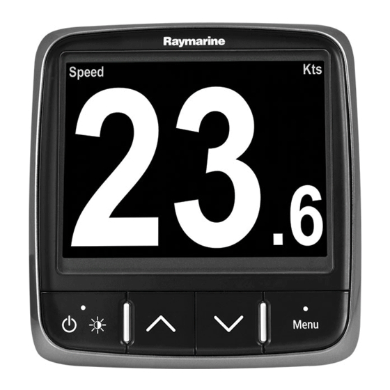
3.2 Instrument controls 3.3 Instrument power Control layout and functions. Powering the instrument on 1. Press and hold the LEFT SOFT button for 1 second, until the Raymarine logo appears. The instrument will load to favorites page one. Powering the display off 1. -
Page 19: Display Settings
3.4 Display settings • Mast • Group 1 — Group 5 Display and shared brightness 2. Use the UP and DOWN buttons to highlight the required group. You can change the brightness of the individual display, or 3. Press the SELECT button to assign the display you are using networked displays. - Page 20 If the unit is part of a network group, the color scheme selected will Example Color Scheme change on all displays which are part of that group. If color is not Day 1 available on the networked displays they will remain unchanged. Display response Setting the display response Setting the response to a low value will provide a more stable...
-
Page 21: Chapter 4: Favorite Pages
Chapter 4: Favorite Pages Chapter contents • 4.1 Favorite pages on page 22 • 4.2 Favorite page frames on page 23 • 4.3 Resetting maximum, minimum and trip data on page 26 • 4.4 Customizing pages on page 27 Favorite Pages... -
Page 22: Favorite
4.1 Favorite pages There are also a number of be-spoke pages you can choose from. Selecting pages 1. Use the UP / DOWN arrows to select between the available pages. Alternatively use the Rollover feature within the setup menu to cycle through the pages automatically. -
Page 23: Favorite
4.2 Favorite page frames Analog frames Each piece of information is displayed in a frame within the page. The frames support a number of different styles and formats for presenting the data. Tri data frame D11838-1 Analog frames provide real-time data in the form of an analog gauge. Analog gauges are only available for full and 2/3 screen frames. - Page 24 Multi gauge frames Minimum value The i70 provides three multi-gauge frames for use as favorite pages Average value which you can see below: Maximum value indictor Multi-gauge — sailing vessel Graph frames D12072-1 Multi-gauge — single engine vessel D11840-1 Graphs provide a means of showing how a particular reading has changed over time.
- Page 25 Race timer frame Multi gauge — twin engine vessel Ra c e tim e r TART D12076-1 D12074-1 The race timer provides the ability for up to 3 countdown timers. Trim tab frame See Race timer chapter for more details. AIS frame D12075-1 The trim tab frame provides information on the position of the trim...
-
Page 26: Resetting Maximum, Minimum And Trip Data
4.3 Resetting maximum, minimum and Rolling road frame trip data The values of some data are accrued over time. These include information such a trip distance, and maximum and average speed. This type of information can be reset as and when required. With the data to be reset displayed on the instrument screen: 1. -
Page 27: Customizing
4.4 Customizing pages 2. Select Favorites page from the menu. 3. Select New page from the menu. You can use the Favorites page menu to change any instrument If you already have the maximum number of pages set up you page to suit your requirements. - Page 28 2. To turn rollover function on select a time interval and press SELECT to confirm. 3. To turn rollover off select Off and press SELECT to confirm. i70 Instrument display User reference...
-
Page 29: Chapter 5 Ais
Chapter 5: AIS Chapter contents • 5.1 AIS Overview on page 30 • 5.2 AIS target symbols on page 31 • 5.3 Setting AIS range on page 33 • 5.4 Viewing AIS target information on page 33 • 5.5 AIS silent mode on page 34... -
Page 30: Ais Overview
5.1 AIS Overview The AIS feature enables you to receive information broadcast by other vessels, and to view these vessels as targets relative to your boat. The AIS feature on i70 is standalone, settings and alarms cannot be shared with other AIS enabled products on your system. How AIS Works AIS uses digital radio signals to broadcast ‘real-time’... -
Page 31: Ais Target Symbols
5.2 AIS target symbols AIS Messages Description Alarm on icon AIS on, transmitting, alarm is active. Your display shows a range of symbols to represent the different types of AIS target. Silent AIS on & user is silent to other vessels. Target type Description Symbol... - Page 32 Target type Description Symbol Target type Description Symbol Aid To Navigation (AToN) AToN target is OFF Land base station target Land base station target target (Real) position. Target red. is ONLINE. Yacht Target vessel type is a yacht. Aid To Navigation (AToN) AToN target is OFF target (Real) position &...
-
Page 33: Setting Ais Range
5.3 Setting AIS range 5.4 Viewing AIS target information You can change the scale of the AIS page by altering the AIS range. Whilst on the AIS page you can view information about AIS targets by following the steps below: 1. -
Page 34: Ais Silent Mode
5.5 AIS silent mode AIS silent mode enables you to disable AIS transmissions AIS silent mode enables you to disable the transmitting functions of your AIS equipment. This is useful when you do not want to transmit your vessel’s AIS data to other AIS receivers, but still wish to receive data from other vessels. -
Page 35: Chapter 6 Race Timer Settings
Chapter 6: Race timer settings Chapter contents • 6.1 Setting the race timer on page 36 • 6.2 Using the race timer on page 36 Race timer settings... -
Page 36: Setting The Race Timer
6.2 Using the race timer 6.1 Setting the race timer If the race timer has not been setup as a favorite page then the Once the Race timer has been set you can use the timer by timer can be accessed from the view data menu: Menu > View following the steps below: data >... -
Page 37: Chapter 7 Multiple Data Sources (Mds)
Chapter 7: Multiple data sources (MDS) Chapter contents • 7.1 Multiple data source (MDS) overview on page 38 • 7.2 Viewing vessel data sources on page 38 • 7.3 Selecting a preferred data source on page 39 Multiple data sources (MDS) -
Page 38: Multiple Data Source (Mds) Overview
7.2 Viewing vessel data sources 7.1 Multiple data source (MDS) overview MDS is a system to manage installations with multiple instances You can view available multiple data sources on a system by of sensors providing the same type of data to vessel displays and following the steps below: systems. -
Page 39: Selecting A Preferred Data Source
7.3 Selecting a preferred data source To select a preferred data source for your system: 1. Go to the MDS menu: Main menu > Setup > System setup > Multiple data source. 2. Press OPTIONS. 3. Highlight Selection and press SELECT. 4. - Page 40 i70 Instrument display User reference...
-
Page 41: Chapter 8 Instrument Alarms
Chapter 8: Instrument alarms Chapter contents • 8.1 Alarms on page 42 Instrument alarms... -
Page 42: Alarms
8.1 Alarms Man overboard alarm In the event of a Man Overboard (MOB) alarm, the instrument Alarms are used to alert you to a situation or hazard requiring your provides a range of information to help find the MOB target. attention. - Page 43 Category Alarm Content Category Alarm Content Depth Deep Alarm • On Temperature Sea Temp. High Alarm • On • Off (default) • Off (default) Adjust • 0 — xxx FT Adjust • 0 — 50ºC • 100 ft (default) • 10ºC (default) Depth Shallow Anchor Alarm...
- Page 44 Category Alarm Content Category Alarm Content Wind AWA Low Alarm • On Other Alarm Clock Alarm • On Apparent Wind • Off (default) • Off (default) Angle low Adjust • 0 — 180º Time • 12:00 am — 12:00 pm •...
- Page 45 Category Alarm Content Other AIS Alarm Safety • On messages • Off (default) Dangerous • On target • Off (default) Safe zone • (0.1 , 0.2, 0.5, 1.0, 2.0) nm • (0.1 , 0.2, 0.5, 1.0, 2.0) sm • (0.2, 0.5, 1.0, 2.0, 5.0) km Time to safe •...
- Page 46 i70 Instrument display User reference...
-
Page 47: Chapter 9 Quick Options
Chapter 9: Quick options Chapter contents • 9.1 Quick options menu on page 48 • 9.2 Quick options menu items on page 48 Quick options... -
Page 48: Quick Options Menu
9.1 Quick options menu 9.2 Quick options menu items Depending on the page being displayed different quick options are The Quick options menu is a dynamic menu which displays menu available as follows: items relative to the items displayed on the favourites page you are on. - Page 49 Page displayed Quick options available Minimum TWA Reset Min. TWA Maximum TWS Reset Max. TWS Minimum TWS Reset Min. TWS Race Timer Start timer Stop timer Reset timer Adjust start times Graph Time scale (View data) page Add to favorites View AIS targets —...
- Page 50 i70 Instrument display User reference...
-
Page 51: Chapter 10 View Data
Chapter 10: View data Chapter contents • 10.1 Data views on page 52 • 10.2 Viewing data on page 57 View data... -
Page 52: Data Views
10.1 Data views Menu item / description Settings / operation Engine • Boost pressure Note: The data described in the table below is dependent on the configuration of your system, so some items may not be • Coolant pressure applicable to your vessel. •... - Page 53 Menu item / description Settings / operation Menu item / description Settings / operation Fuel Fuel management is dependant on a Environment • Air temperature suitable fuel or engine management • Air temperature history system being available on the SeaTalk network.
- Page 54 Menu item / description Settings / operation Menu item / description Settings / operation • COG Navigation • Active waypoint name • Waypoint ID • COG history • COG + SOG pair • CMG • HDOP • CMG history • BTW •...
- Page 55 Menu item / description Settings / operation Speed • Average speed • Boat speed & SOG • Max speed • Speed • Speed history • Trolling • VMG windward • VMG windward history • VMG WPT • VMG WPT history Time •...
- Page 56 Menu item / description Settings / operation Menu item / description Settings / operation Wind • AWA • TWA & VMG pair • AWA history • TWA max • AWA & AWS pair • TWA min • AWA(CH) & AWS pair •...
-
Page 57: Viewing Data
10.2 Viewing data You can use the View data menu to view information which has not been added to favorite pages. 1. Select View data menu from the main menu. 2. From the Select Category menu choose the data category. 3. - Page 58 i70 Instrument display User reference...
-
Page 59: Chapter 11 Setup Menu
Chapter 11: Setup menu Chapter contents • 11.1 Setup menu on page 60 Setup menu... -
Page 60: Setup Menu
11.1 Setup menu Menu item Description Options Simulator Enables or disables • On The setup menu provides a range of tools and settings to configure simulator mode, the instrument display. • Off which allows you to Menu item Description Options practice operating your instrument display Transducer setup... - Page 61 Transducer setup menu The Transducer setup menu provides the functions to enable setup and calibrate connected transducers. Menu item Description Options Depth Enables setup and calibration of depth transducers Details displays can supply information about the and provides the following options: installed transducer or interface such as Serial No.
- Page 62 Menu item Description Options Wind Enables setup and calibration of wind transducers Details displays information about the installed and provides the following options: transducer, Serial No. and Software version etc. Calibrate vane- follow the on screen instructions to • Wind detail calibrate the wind vane.
- Page 63 Menu item Description Options Temperature offset: • xxx ºC or ºF DT800 Enables setup and calibration of DT (Depth, and DT800 details displays information about the Temperature) smart transducers and provides the installed transducer, Serial No. and Software version following options: etc.
- Page 64 User preference menu The User preference menu enables users to customize user settings as detailed in the table below: Menu item Description Options Time & date These options enable you to customize the date Date format: and time format to your requirements. You can •...
- Page 65 Menu item Description Options Wind speed: • kts — knots. • m/s — metres per second. Temperature: • ºC — degrees centigrade. • ºF — degrees fahrenheit. Flow rate • UK Gal/H — UK gallons per hour. • US Gal/H — US gallons per hour. •...
- Page 66 Menu item Description Options Language Determines the language that will be used for all • Chinese on-screen text, labels, menus and options. • Croatian • Danish • Dutch • English — UK • English — US • Finnish • French •...
- Page 67 Menu item Description Options Vessel type Determines the default setup of the unit and favorite • Race sail pages • Sail cruiser • Catamaran • Workboat • RIB • Outboard speed boat • Inboard speed boat • Power cruiser 1 •...
- Page 68 Menu item Description Options Variation range: • -30º — +30º i70 Instrument display User reference...
- Page 69 System setup menu The System setup menu enables users to customize user settings as detailed in the table below: Menu item Description Options Network group This allows you to add multiple units together in a Pre-defined groups group so that when the color scheme or brightness is •...
- Page 70 Menu item Description Options Multiple data sources This allows you to view and select preferred data Select data source sources. • GPS position • Select data source • Heading • Data source found • Depth • Data source details • Speed •...
- Page 71 Simulator The Simulator mode enables you to practice operating your display without live data from a transducer or other connected peripherals. The simulator mode is switched on/off in the Simulator option from the Setup Menu. Note: Raymarine recommends that you do NOT use the simulator mode whilst navigating.
- Page 72 Diagnostics You can access diagnostics details from the Setup > Diagnostics menu option and can view information relating to: Menu item Description Options About display Allows you to view information about the instrument • Software version display you are using: •...
- Page 73 Menu item Description Options Key beep Enables you to turn on and off the audible beeps • On when keys are pressed • Off Self test The product has a built in self test which can help • Memory test to diagnose faults.
- Page 74 i70 Instrument display User reference...
-
Page 75: Chapter 12 Maintaining Your Display
Chapter 12: Maintaining your display Chapter contents • 12.1 Service and maintenance on page 76 • 12.2 Routine equipment checks on page 76 • 12.3 Cleaning on page 77 • 12.4 Cleaning the display screen on page 77 • 12.5 Performing a factory reset on page 78 Maintaining your display... -
Page 76: Service And Maintenance
12.2 Routine equipment checks 12.1 Service and maintenance This product contains no user serviceable components. Please Raymarine strongly recommends that you complete a number of refer all maintenance and repair to authorized Raymarine dealers. routine checks to ensure the correct and reliable operation of your Unauthorized repair may affect your warranty. -
Page 77: Cleaning
12.3 Cleaning 12.4 Cleaning the display screen Best cleaning practices. A coating is applied to the display screen. This makes it water repellent, and prevents glare. To avoid damaging this coating, follow When cleaning this product: this procedure: • Do NOT wipe the display screen with a dry cloth, as this could 1. -
Page 78: Performing A Factory Reset
12.5 Performing a factory reset To reset your i70 to factory settings follow the steps below. Note: Performing a factory reset will erase all saved data and customized settings. 1. Press the RIGHT SOFT button to open the main menu. 2. -
Page 79: Chapter 13 Technical Support
Chapter 13: Technical support Chapter contents • 13.1 Raymarine customer support on page 80 • 13.2 Viewing product information on page 80 Technical support... -
Page 80: Raymarine Customer Support
13.1 Raymarine customer support 13.2 Viewing product information Raymarine provides a comprehensive customer support service. 1. From the main menu scroll to Set Up and press the SELECT key. You can contact customer support through the Raymarine website, 2. From the Set Up menu scroll to Diagnostics and press the telephone and email. - Page 82 www.ra ym a rin e .c o m...
Need help?
Do you have a question about the Raymarine i70 and is the answer not in the manual?
Questions and answers