
Subscribe to Our Youtube Channel
Related Manuals for Protec Cirrus Pro Series


Summary of Contents for Protec Cirrus Pro Series
- Page 1 CIRRUS PRO ASPIRATING FIRE DETECTOR User Manual and Responsibilities Protec Fire Detection (Export) Ltd, Protec House, Churchill Way, Nelson, Lancashire. BB9 6RT. Telephone: +44 (0) 1282 717171 Fax: +44 (0) 1282 717273...
- Page 2 Protec Fire Detection (Export) Ltd's obligation under this Warranty relates to the original purchaser and is limited to the return of the purchase price or, at Protec Fire Detection (Export) Ltd's sole discretion, to the repair or replacement of the detector or any of its parts which, in our opinion and upon examination prove to be defective.
- Page 3 Issue Date Author First Issue 26/04/05 Minor Changes – Display Software v1.09 02/06/05 UL Information introduced 14/02/06 References to Bellows removed 2/11/12 Airflow thermistor annual check 09/12/13 93-523-23 Issue 4 Page 3 of 21 CirrusPro User Manual...
-
Page 4: Table Of Contents
CONTENTS INTRODUCTION ........................5 Models and Equipment Covered ....................6 UL and ULC information. Pro100, 200, 200+, 200D, 200D+, 200DSC and 200DSC+ ..... 7 UL and ULC information Pro X4 ....................9 PERIODIC CHECKS AND MAINTENANCE ................11 Periodic Checks ........................11 2.1.1 Daily Checks ........................ -
Page 5: Introduction
Introduction This manual details the methods employed to install, commission and service the CirrusPro Series Aspirating Fire Detectors. Background Background It is known that particles smaller than the wavelength of visible light occur spontaneously as a material is overheated, and in numbers far above those present in a normal ambient environment. CirrusPro Detectors utilise the Wilson Cloud Chamber principle to detect the sub micron particles that are generated at the incipient, and all other stages of fire. -
Page 6: Models And Equipment Covered
Models and Equipment Covered CirrusPro 100 Up to 100m of 25mm diameter sampling pipe. Single sampling pipe ‘inlet’ port. CirrusPro 200 Up to 200m of 25mm diameter sampling pipe. Four, sampling pipe ‘inlet’ ports. CirrusPro 200D As CirrusPro 200 with built in Display Panel (See CirrusPro RDP). CirrusPro 200DSC As CirrusPro 200D but with four, scanned, sampling pipe ‘inlet’... -
Page 7: Ul And Ulc Information. Pro100, 200, 200+, 200D, 200D+, 200Dsc And 200Dsc
UL and ULC information. Pro100, 200, 200+, 200D, 200D+, 200DSC and 200DSC+ The following information is required to ensure the units compliance with the UL listing for UL 268 & CAN/ULC-S529-02 Detection Principle: Cloud Chamber Maximum Protected Area: Pro 100 10,000 square feet (929.03 square meters) Pro 200 20000 square feet (1858.06 square meters) - Page 8 17.32” x 15.15” x 5.51” (440mm x 385mm x 140mm) The piping diagram for each system will be supplied by Air Sampling System: Protec Fire Detection (Export) or an authorized representative. This diagram will indicate tubing size, as well as approximate lengths to each sampling point.
-
Page 9: Ul And Ulc Information Pro X4
UL and ULC information Pro X4 The following information is required to ensure the units compliance with the UL listing for UL 268 & CAN/ULC-S529-02 Cloud Chamber Detection Principle: Maximum Intended Protected Area: 43,200 square feet (4013 square meters) 4 zones total 10800 square feet (1003.25 square meters) per zone 900 square feet (83.604 square meters) per sampling head or point... - Page 10 17.32” x 15.15” x 5.51” (440mm x 385mm x 140mm) Cabinet: The piping diagram for each system will be supplied by Air Sampling System: Protec Fire Detection (Export) or an authorized representative. This diagram will indicate tubing size, as well as approximate lengths to each sampling point. Gain Settings...
-
Page 11: Periodic Checks And Maintenance
Check that any fault reported previously has been attended to. • 2.1.2 Three-monthly Checks The following must be performed EVERY THREE MONTHS by Protec Fire Detection (Export) Ltd or an authorised representative: Check the Event Log to determine any abnormalities. - Page 12 Inspect and clean if necessary airflow thermistor. The thermistor can be seen from the top of the • manifold. IMPORTANT: Ensure the unit is switched off. Use a small brush to brush away any accumulated dust particles. Be careful not to move the alignment of the thermistor. The thermistor must be aligned central to the hole in the correct orientation, refer to the diagrams above.
-
Page 13: User Guide
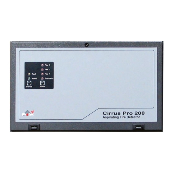
User Guide Front Panel Indications and Controls All CirrusPro models have a small control panel with 6 LED indicators and 2 push buttons: Indications There are 4 levels of alarm, Pre Alarm and Fire levels 1, 2 and 3. The points at which these levels are set can be examined in the Sensitivity Settings section of the commissioning menu on the PC. - Page 14 The Up and Down keys move between the units. Select accepts the current highlighted detector unit, request status and displays the following, depending on model: Showing the current particle levels for the sample pipes. Pressing Menu requires a password. Use the + and – to select the number and press Enter. The low security codes is factory pre set to 112233, although, this can be changed from the display see section 3.2.6.
-
Page 15: Main Options Menu
3.2.1 Main Options Menu The menu options available are as shown. Use the Down Key to move to the required option. Press Select to move to that menu Option. Pressing Exit from this menu will revert back to the particle level display. It will then be necessary to enter the security code again to return to the Main Options Menu. -
Page 16: Unit/Pipe Text
3.2.3 Unit/pipe text The display receives the text from the unit. Use Up, Down and Edit to select the text to be edited. Then use Left, Right and Exit keys to select a character. To change a character, use + and – to scroll through the symbols and alphabet in the following order: !”£$%&’()*+,-./0123456789:;<=>?@ABCDEFGHIJKLMNOPQRSTUVWXYZ[\]_’abcdefghijklmnopqrstuvwxyz After editing as required, press Exit to return to the Unit / Pipe Text display. -
Page 17: Historic Graph
Pressing Fires changes the display to show just Fault events. Pressing Fault returns to showing all events. 3.2.5 Historic Graph The Historic Graph shows a period of about three days, with about 10 days stored. The amount of data is dependent on what has happened during the recording period. The amount of data stored increases during fire and pre alarm events. -
Page 18: Service Information
Pressing Exit leaves this display without changing the code. Record the User Security code here: User Code 3.2.7 Service Information Acceptable Values: Pump Pressure - > 5.7 psi Supply voltage - 19V to 30V LED current is - 0.26mA to 5.67mA Airflow Refer to Pipe Calculation Average time between fills... -
Page 19: Fault Finding
Fault Finding Internal diagnostics monitor for faults that may normal running. Fault List The list below shows all the possible faults and their codes: 1 Processor fault 12 Low supply voltage 2 Corrupt eeprom 13 Algotec fault 3 Supply fault 14 Unit cold Fault 4 No water 15 Unit disabled... -
Page 20: Detector Specification
Detector Specification Physical Data varies with model and are not given here Supply Voltage: 19 - 30VDC Humidity: 10 - 95%RH, non-condensing Temperature: 0 - 38°C IP Rating: IP30 Cable Access: 20mm knock Cable Termination: Screw terminal blocks (0.2 - 2.5mm2, 30 - 12AWG) Pipe ID: 19 to 25mm (preferred OD 25mm) Alarm Indications:... - Page 21 Cirrus Pro Series Aspirating Fire Detectors Worldwide Manufacturer PROTEC FIRE DETECTION (EXPORT) LIMITED Protec House, Phone: +44 1282 717171 Churchill Way, Fax: +44 1282 717273 Nelson, E-mail: sales@protec.co.uk Lancashire, England. BB9 6RT. 93-523-23 Issue 4 Page 21 of 21 CirrusPro User Manual...
Need help?
Do you have a question about the Cirrus Pro Series and is the answer not in the manual?
Questions and answers
hi we have 3 units in a Data centre. all 3 units go into fire but not much activity happening. we have energy units pulling load of up to 100% in the room for the entire day and the pipes didn't heat up or have a temperature rise. pipes currently at 36 deg
Low activity in Protec Series units during a fire situation, while energy units are pulling a full load, could be caused by fault conditions such as:
- No water (Fault Code 4)
- Water fill fault (Fault Code 8)
- Airflow fault (Fault Code 9)
- Sample blocked (Fault Code 20)
- Purge blocked (Fault Code 21)
- Low supply voltage (Fault Code 12)
- Algotec fault (Fault Code 13)
These faults can prevent proper operation and reduce detection sensitivity, even during a fire event.
This answer is automatically generated
What do I look at on a low water fault. How high should it be
For a low water fault on a Protec Cirrus Pro Series, check the following:
- Ensure the water bottle is refilled with distilled or de-ionized water.
- Verify that there are no leaks or blockages in the water system.
- Confirm that the water fill mechanism is functioning correctly.
The document does not specify an exact required water level, but the system should be replenished as needed based on environmental conditions.
This answer is automatically generated