
Related Manuals for POSEIDON Jetstream


Summary of Contents for POSEIDON Jetstream
- Page 1 Important Important Fault-tracing Fault-tracing Jetstream Jetstream Cyklon Cyklon Triton Triton SERVICE SERVICE Service tools Service tools MANUAL 1999 MANUAL 1999 ® ® Spare parts Spare parts Service-Kit Service-Kit...
- Page 2 This manual contains preliminary servicing instructions for the Poseidon breathing regulators. It is intended to serve as a guide for repairs and servicing carried out by Poseidon Diving Systems. The instructions given in this manual are based on the assumption that special tools are used and are based on our experience.
- Page 3 FUNCTION POSEIDON breathing regulator is a two-stage regulator where the first stage is a diaphragm-actuated reducing valve, whith reduces the primary pressure (Cylinder pressure) to approx. 145 PSI. The reduced pressure (the secondar’y pressure) then goes via the regulator hose to the second stage where the air supply is automatically regulated to the convenience of the diver.
- Page 4 Technical data Repair instructions second-stage demand valve 2725, 2941, 2961, 3546 Repair instructions first stage 2801, 2962, 3580 Repair instructions first stage 2808, 3580-10, 3790, 3790-10 Final adjustment Jetstream Final adjustment Oceanair...
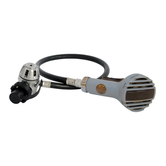
- Page 5 JETSTREAM Poseidon Jetstream BREATHING REGULATOR Art. No 2960 USA: Poseidon Odin Primary pressure................Max. 4350 PSI / 300 bar Secondary pressure ................Max. 145 PSI 10 bar Air flow ....................Approx. 1600 l/min Inhalation resistance ................Max. 40 mm of water Exhalation resistance ...............Max. 20 mm of water...
- Page 6 Outlet connections: One outlet marked R for second stage (max. airflow)..................UNF 3/8’’ - secondary pressure Three outlets marked LP for Jetstream octopus, drysuits, stadjacket................UNF 3/8’’ -secondary pressure Two outlets marked HP for pressure gauge......UNF 7/16’’ -primary pressure SECOND STAGE VALVE Art.
- Page 7 JETSTREAM Poseidon Oceanair BREATHING REGULATOR Art. No 2940 USA: Poseidon Thor Primary pressure................Max. 4350 PSI / 300 bar Secondary pressure ................Max. 181 PSI / 12.5 bar Air flow ....................Approx. 1500 1/ min Inhalation resistance ................Max. 40 mm of water Exhalation resistance ...............Max. 20 mm of water...
- Page 8 JETSTREAM REPAIR INSTRUCTIONS SECOND STAGE DEMAND VALVE EXPLODED VIEW Art. No. 2725, 2941, 2961, 3546 Low pressure hose with saftey valve Low pressure valve Servo valve Housing complete Switch 1.0:E10...
- Page 9 JETSTREAM SECOND STAGE 2710, 2941, 2961, 3546 Removal: 1. Disconnect the low pressure hose from the second stage. 2. Remove the low pressure valve from the housing (15) with a screwdriver. Make sure the servo valve needle is not bent. Be sure...
- Page 10 JETSTREAM Removal: 1. Remove the servo valve (14). 2. Unscrew the stop screw (9) and remove the valve tube (12). Remove the o-rings (11) (13) with an o-ring remover. Make sure the sealing surfaces are not damaged. 3. Remove the rubber plate (10).
- Page 11 JETSTREAM When servicing the regulator the following parts should be replaced: See chapter Servicekit. 1. All o-rings. Also the ones in the low pressure hose. CLEANING: If corrosion or salt deposits occurs, place all metal parts – concentrated Hempocid* or 15% Hydrochloric acid for about 10 minutes.
- Page 12 JETSTREAM SECOND STAGE Assembly: 1. Mount the o-rings (5,3) on the valve housing (4). Use the tools. See diagram. 2. Install the valve insert (6) in the valve housing (4). 3. Place the o-ring (7) in the groove of the valve insert (6).
- Page 13 JETSTREAM 5. Install the o-rings (11,13) on the valve tube (12). Grease the threads and the o-rings. 6. Screw in the valve tube (12) until about 2 mm space remains as illustrated. 7. Install the rubber plate (10). Screw in the set screw (9).
- Page 14 JETSTREAM Assembly: 1. Fit the purge button in the cover (25) for the second stage. Make sure that the spring is undamaged. 2. Position the diaphragm (24) with the diaphragm washer facing down wards and the hole positioned as illustrated.
- Page 15 JETSTREAM REPAIR INSTRUCTIONS FIRST STAGE REDUCING VALVE EXPLODED VIEW Art. No. 2801, 2808, 2962, 3257, 3580, 3585 JETSTREAM - YOKE CYKLON 5000 - YOKE ANTI-FREEZE CUP DIFFERENT CONNECTION SECONDARY PART PRIMARY PART BALANCING PART 1.0:E17...
- Page 16 JETSTREAM FIRST STAGE VALVE 2801, 2808, 2962, 3257, 3580, 3585 Secondary side: 1. Disconnect the low pressure hose from the first stage valve using a 13 mm open end wrench. 2. Remove the o-ring from the low pressure hose. Make sure the sealing surfaces are not damaged.
- Page 17 JETSTREAM BALANCE HOUSING Removal: Place the first-stage valve with the balanced housing facing upwards. 1. Steady the balance housing with a special wrench. Then remove the blind screw (25) with a 5 mm Allen wrench. Remove the o-ring(24) with an o-ring remover.
- Page 18 JETSTREAM FIRST STAGE 2962, 3257, 3580, 3585 Removal: 1. Remove the protective cap (26). 2. Remove the locking screw (27) with a 6 mm Allen wrench. Remove the o-ring (28) and the cupfilter (30). 3. Place the first stage in the fixture.
- Page 19 JETSTREAM FIRST STAGE 2801 Removal: 1. Remove the protective cap (3 1). 2. Remove the locking screw (27) with an 8.5 mm screwdriver. Remove the cup filter (28). 3. Place the first stage in the fixture. Remove the high pressure valve housing (33) with a 6 mm Allen wrench.
- Page 20 JETSTREAM FIRST STAGE 2801, 3257 10, 3585 10 Removal: 1. Remove the protective cap (24). Unscrew the knob (25). 2. Remove the locking screw (27) with an 8.5 mm screwdriver. Remove the cup filter (28). 3. Remove the connection (29) with a 6 mm Allen wrench.
- Page 21 JETSTREAM FIRST STAGE 2801, 2808, 2962, 3257, 3580, 3585 6. Remove the valve seat (15) with a valve seat remover. 7. Remove the o-ring (14) with an oring remover. Make sure the sealing surface is not damaged. 8. Remove the valve housing from the fixture.
- Page 22 JETSTREAM CLEANING: If corrosion or salt deposits occurs, place all metal parts – concentrated Hempocid* or 15% Hydrochloric acid for about 10 minutes. Then, rince the parts When servicing the regulator the thoroughly and blow dry with air. following parts should be replaced: The synthetic parts in the second See chapter Servicekit.
- Page 23 JETSTREAM 3. The valve housing (11). Check to make sure the threads and also the sealing surfaces for the o-rings are undamaged. 4. The connections (29,31 or 33). Check to make sure the sealing surfaces for the o-rings are un- damaged.
- Page 24 JETSTREAM Assembly 1. Install the o-rings (9) and (12) on the blind screws (10) and (13). Lubricate through the outlets. 2. Screw in the blind screws in the LP- HP outlets. Use a 5 mm Allen wrench and tighten up by hand.
- Page 25 JETSTREAM FIRST STAGE 2962, 3257, 3580, 3585 Assembly: 1. Install the o-ring (3 1) on the connection (30). Lubricate the o-ring and the thread. 2. Install the wheel (33) on the connection. 3. Screw the wheel connection assembly into, the valve housing assembly with a 6 mm Allen wrench.
- Page 26 JETSTREAM FIRST STAGE 2801, 3257 10, 3585 10 Assembly: 1. Install the o-ring (30) on the connection (29). Lubricate the thread and the o-ring. 2. Place the connection (29) in the Yoke (26) and screw the connec- tion into the valve housing (13) using a 6 mm Allen wrench.
- Page 27 JETSTREAM FIRST STAGE 2808 Assembly: 1. Install the o-rings (30, 32) on the connection (33). Grease the o-ring (30) and thread. 2. Fit the connection (33) to the wheel (34) and screw it into the valve housing (13) with a 6 mm Allen wrench.
- Page 28 JETSTREAM FIRST STAGE BALANCED HOUSING 1. Install the o-ring (24) on the blind screw G 1/8’’ (25). 2. Grease the inside of balanced housing (21). 3. Install the spring guide (22) and the spring (23). Screw in the blind screw (11) with a 5 mm Allen wrench.
- Page 29 JETSTREAM 7. Turn the valve housing with the secondary side upwards. 8. Install the valve needle (10). At previous models the needle was beveled in one edge. The bevel should in these cases be pointed downwards. 9. Install the lower diaphragm centre...
- Page 30 JETSTREAM REPAIR INSTRUCTIONS FIRST STAGE REDUCING VALVE 3790 - First stage G 5/8” 3790-10 - First stage YOKE ANTI-FREEZE CAP DIFFERENT CONNECTIONS YOKE G 5/8’’ SAFETY VALVE 1.0:E32...
- Page 31 JETSTREAM FIRST STAGE VALVE 3790 Secondary side: 1. Disconnect the low pressure hose from the first stage valve using a 13 mm open end wrench. 2. Remove the o-ring (30) from the low pressure hose with the o- ring remover.
- Page 32 JETSTREAM FIRST STAGE VALVE 3790 Removal: 1. Remove the pressure adjusting screw (1) with a 6 mm Allen wrench and remove the spring (2 and 3). 2. Remove the cover (4) using a 27 mm crowsfoot and the upper diaphragm center (5).
- Page 33 JETSTREAM FIRST STAGE VALVE 3790 Removal: 1. Remove the valve centre, upper (6) and the diaphragm (7). 2. Remove the diaphragm centre, lower (8) and the valve needle (9). 3. Remove the valve centre, lower (10) and the o-ring (11) with an o- ring remover.
- Page 34 JETSTREAM FIRST STAGE VALVE 3790 Removal: 1. Remove the blind screw (29 and 31) with a 5 mm Allen wrench. Remove the o-rings (30 and 32) with an o-ring remover. Make sure the sealing surfaces are not damaged. 2. Remove the locking screw (35) with a 4mm Allen wrench.
- Page 35 JETSTREAM FIRST STAGE VALVE, 3790 When servicing the regulator the following parts should be replaced: (see chapter Servicekit) 1. All o-rings 2. Diaphragm 3. Cup filter 4. Valve seat 5. Washer 6. Valve sealing Checking: Check the following parts to make sure the sealing surfaces are undamaged.
- Page 36 JETSTREAM FIRST STAGE VALVE 3790 Assembly: 1. Install the o-rings(30 and 32) on the blind screws (29 and 31). Lubricate the outlets. 2. Screw the blind screws in the LP-HP outlets. Use a 5 mm hexagon spanner and tighten up by hand.
- Page 37 JETSTREAM FIRST STAGE VALVE 3790 Assembly: 1. Lubricate the valve housing (20). 2. Place on the assembly drift A: -washer, steel (17) -O-ring (18) -washer, teflon (19) 3. Install the valve housing. Lubricate the washers and the o-ring. 4. Install the o-ring (13) on the valve seat (14).
- Page 38 JETSTREAM FIRST STAGE VALVE 3790 Assembly: 1. Place on the assembly fixture B: - valve centre, lowér (10) - o-ring (11), lubricate - valve seat (14) with o-ring downwards - valve piston (15), lubricate, and pressure spring (16) on valve piston.
- Page 39 JETSTREAM FIRST STAGE VALVE 3790 Assembly: 1. Install the diaphragm centre, upper (5) in the valve housing (20). 2. Grease the thread on the cover (4) and tighten up by hand. 3. Check to make sure that the parts are correctly installed by pressing at the valve centre.
- Page 40 JETSTREAM FIRST STAGE VALVE 3790 Assembly: 1. Place the valve housing (20) in a fixture. 2. Tighten the cover for valve housing with a torque wrench (30 Nm) and an open ended insert tool 27 mm. 3. Tighten the connection with a torque wrench (30 Nm) and holder insert tool/ bits.
- Page 41 JETSTREAM TESTING AND ADJUSTMENT OF REGULATOR JETSTREAM Art. No. 2960, 3960 First stage valve: water tank and check to make sure that the valve 1. Connect the regulator to the test equipment. is absolutely tight. 2. Connect the test manometer hose to one of the 5.
- Page 42 JETSTREAM TESTING AND ADJUSTMENT OF THE REGULATOR OCEANAIR Art. No. 2940 First stage valve: water tank and check to make sure that the valve 1. Connect the regulator to the test equipment. is absolutely tight. 5. Move the low pressure valve to the second stage 2.
- Page 43 Technical data Repair instructions second-stage demand valve Repair instructions first stage 2305, 2422, 3070 Repair instructions first stage 3257, 3585 Repair instructions first stage 3720, 3720-10 Final adjustment Cyklon 300 Final adjustment Cyklon 5000...
- Page 44 CYKLON Poseidon Cyklon 300 BREATHING REGULATOR Art. No 2980 Primary pressure................Max. 4350 PSI / 300 bar Secondary pressure ................Max. 181 PSI / 12.5 bar Air flow ....................Approximately 800 l/min Inhalation resistance at 115 l/min..........Max. 40 mm of water Exhalation resistance ...............Max. 20 mm of water...
- Page 45 CYKLON Poseidon Cyklon 5000 BREATHING REGULATOR Art. No 2950 Primary pressure................Max. 4350 PSI / 300 bar Secondary pressure ................Max. 174 PSI / 12 bar Air flow ....................Approx. 1050 l/min Inhalation resistance at 115 l/min..........Max. 40 mm of water Exhalation resistance ..............Max. 20 mm of water...
- Page 46 CYKLON Poseidon Cyklon 5000 BREATHING REGULATOR Art. No 3950 Primary pressure................Max. 4350 PSI / 300 bar Secondary pressure ................Max. 174 PSI / 12 bar Air flow ....................Approx. 1050 l/min Inhalation resistance at 115 l/min..........Max. 40 mm of water Exhalation resistance ...............Max. 20 mm of water...
- Page 47 CYKLON REPAIR INSTRUCTIONS SECOND STAGE DEMAND VALVE EXPLODED VIEW SECOND STAGE 1133 Low pressure hose Low pressure valve Mouth-piece Mouth-piece tube Diaphram house 1.0:E48...
- Page 48 CYKLON SECOND STAGE 1133, 3224, 3354, 3536 Removal: 1. Disconnect the low pressure hose from the second stage with a 17 mm. open wrench. Remove the oring (2) with an o-rings remover. 2. Remove the diaphragm housing (27) from the mouth piece tube. 3.
- Page 49 CYKLON 1. Remove the locking ring (25) with an awl. Support the diaphragm house, see diagram. Make sure that the sealing surface for the exhalation diaphragm is not damaged. 2. Remove the cover (24) and the inhalation diaphragm (23). Removal: Push out the purge button IMPORTANT! The purge button (26) should not be removed if it...
- Page 50 CYKLON 1. Cut off the locking strap (17) with cutting pliers. 2. Remove the mouth-piece (16) and the o-ring (12). 1. Remove the lever pin (11). 2. Remove the operating device (14). 3. Remove the o-ring (12). 4. Unserew the valve seat (5) with an 8.5 mm screwdriver.
- Page 51 CYKLON When servicing the regulator the following parts should be replaced: See chapter Servicekit. 1. All o-rings, including the one in the low-pressure hose. 2. Rubber plate (7). CLEANING: If corrosion or salt deposits occurs, place all metal parts – concentrated Hempocid* or 15% Hydrochloric acid for about 10 minutes.
- Page 52 CYKLON Assembly: Install the ejector sleeve (13) on the valve housing (10). Press the sleeve into the low pressure valve so the slits of the sleeve are exceedingly small. Lubricate: Grease: Oil: Sealing surfaces 1. Install the o-ring (6) on the valve seat (5).
- Page 53 CYKLON 1. Place the valve housing on a drift seated on a block. Press the valve housing down, compressing the spring. Keep the flat part of the valve piston parallel with the horizontal slot in the end of the valve housing. Move the valve piston up and down a few times to check for freedom of movement.
- Page 54 CYKLON 1. Install the o-ring (12). Lubricate. See diagram. 2. Install the mouth piece (16) and the plastic band (17). Tighten and cut off plasticband with plastic band pliers. 3. Install the o-ring .(12) 4. Lubricate the threads on the mouth piece 5.
- Page 55 CYKLON 1. Install the purge button (26) in the cover (24).Screw the button in the cover-cavity 2. Install the inhalation diaphragm (23) on the diaphragm housing (22). 3. Seat the lip on the diaphragm into the recess on the inner rim of the diaphragm housing.
- Page 56 CYKLON 1. Install the exhalation diaphragm (21) on the diaphragm housing. Control that the diaphragm is packing on the diaphragm housing. 2. Install exhalation diaphragm cover (20) and locking ring (19). 3. Install the diaphragm housing on the mouthpiece tube. Be sure to slip the operating device into the diaphragm guide sleeve.
- Page 57 CYKLON REPAIR INSTRUCTIONS FIRST STAGE REDUCING VALVE EXPLODED VIEW Art. No. 2305, 2422, 3070 ANTIFREEZE CUP SECONDARY PART PRIMARY PART YOKE CONNECTION 1.0:E58...
- Page 58 CYKLON FIRST STAGE VALVE 2305, 2422, 3070 Secondary side: Removal: Place the first-stage valve in fixture with the secondary side facing upwards. 1. Remove the pressure adjusting screw (1) with a 6 mm hexagon spanner, and remove the spring (2) and (3). 2.
- Page 59 CYKLON FIRST STAGE 3070 (2422) 1. Remove the locking screw (23) with a 6 mm Allen wrench. 20 Remove the o- ring (24), cup filter (21) and o-ring (22). 2. Place the first stage in the fixture. Remove the connection (20) with 6 mm Allen wrench.
- Page 60 CYKLON 1. Remove the valve seat (15) with the valve seat remover. 2. Remove the o-ring (14) with an o-ring remover. Make sure that the sealing surfaces are not damaged. Sealing surfaces 3. Remove the blind screws (9) and (13) with a 5 mm Allen wrench.
- Page 61 CYKLON When servicing the regulator following parts should be replaced: See chapter Servicekit. 1. All o-rings 2. Diaphragm 3. Cup filter 4. Valve seat Cleaning: If corrosion or salt deposits are in evidence, place all metal parts in 15 percent hydro-chloric acid. They should be left in the acid for about 10-15 minutes.
- Page 62 CYKLON Assembly Lubricant: Grease: 1. Install the o-ring (10) on the blind screws (9), low pressure supply and the o-ring (12) on the blind screw (13), high pressure supply. Lubricate the blind screws and the o-rings. 2. Screw in the blind screws in the LP-HP outlets.
- Page 63 CYKLON FIRST STAGE 3070, 2422 1. Install the o-ring (19) on the connection housing (20). Lubricate the o-ring and the thread 2. Install the wheel (18) on the con nection (20). 3. Screw the wheel connection assembly into the valve housing assembly with a 6 mm Allen wrench.
- Page 64 CYKLON 1. Place the upper diaphragm center (5) on the diaphragm in the valve housing. 2. Screw the cover (4) into the valve housing. 3. Lubricate both ends of the spring (2) and (3). Lubricate the threads on the pressure adjusting screw(1).
- Page 65 CYKLON FIRST STAGE 3070, 2422 1. Install the o-ring (22) on the cup type 21), then install the locking screw and o-ring (23). Tighten with a 6 mm Allen wrench. FIRST STAGE 2305 1. Install the cup filter (18) and the locking screw (19) with a 8.5 mm screwdriver.
- Page 66 CYKLON OLD TYPE For assembly of old-type spring housing, please note the following: 1. The upper diaphragm centre must be centered in the mid part. 2. The inner and outer secondary springs shall be set in the middle. 3. Screw carefully on the cover with assembly screw.
- Page 67 CYKLON REPAIR INSTRUCTIONS FIRST STAGE REDUCING VALVE EXPLODED VIEW Art. No. 2801, 2808, 2962, 3257, 3580, 3585 JETSTREAM - YOKE CYKLON 5000 - YOKE ANTI-FREEZE CUP DIFFERENT CONNECTION SECONDARY PART PRIMARY PART BALANCING PART 1.0:E68...
- Page 68 CYKLON FIRST STAGE VALVE 2801, 2808, 2962, 3257, 3580, 3585 Secondary side: 1. Disconnect the low pressure hose from the first stage valve using a 13 mm open end wrench. 2. Remove the o-ring from the low pressure hose. Make sure the sealing surfaces are not damaged.
- Page 69 CYKLON BALANCE HOUSING Removal: Place the first-stage valve with the balanced housing facing upwards. 1. Steady the balance housing with a special wrench. Then remove the blind screw (25) with a 5 mm Allen wrench. Remove the o-ring(24) with an o-ring remover.
- Page 70 CYKLON FIRST STAGE 2962, 3257, 3580, 3585 Removal: 1. Remove the protective cap (26). 2. Remove the locking screw (27) with a 6 mm Allen wrench. Remove the o-ring (28) and the cupfilter (30). 3. Place the first stage in the fixture.
- Page 71 CYKLON FIRST STAGE 2801 Removal: 1. Remove the protective cap (3 1). 2. Remove the locking screw (27) with an 8.5 mm screwdriver. Remove the cup filter (28). 3. Place the first stage in the fixture. Remove the high pressure valve housing (33) with a 6 mm Allen wrench.
- Page 72 CYKLON FIRST STAGE 2801, 3257 10, 3585 10 Removal: 1. Remove the protective cap (24). Unscrew the knob (25). 2. Remove the locking screw (27) with an 8.5 mm screwdriver. Remove the cup filter (28). 3. Remove the connection (29) with a 6 mm Allen wrench.
- Page 73 CYKLON FIRST STAGE 2801, 2808, 2962, 3257, 3580, 3585 6. Remove the valve seat (15) with a valve seat remover. 7. Remove the o-ring (14) with an oring remover. Make sure the sealing surface is not damaged. 8. Remove the valve housing from the fixture.
- Page 74 CYKLON CLEANING: If corrosion or salt deposits occurs, place all metal parts – concentrated Hempocid* or 15% Hydrochloric acid for about 10 minutes. Then, rince the parts thoroughly and blow dry with air. When servicing the regulator the The synthetic parts in the second stage following parts should be replaced: must not be treated with solvent.
- Page 75 CYKLON 3. The valve housing (11). Check to make sure the threads and also the sealing surfaces for the o-rings are undamaged. 4. The connections (29,31 or 33). Check to make sure the sealing surfaces for the o-rings are un- damaged.
- Page 76 CYKLON Assembly 1. Install the o-rings (9) and (12) on the blind screws (10) and (13). Lubricate through the outlets. 2. Screw in the blind screws in the LP- HP outlets. Use a 5 mm Allen wrench and tighten up by hand. 3.
- Page 77 CYKLON FIRST STAGE 2962, 3257, 3580, 3585 Assembly: 1. Install the o-ring (3 1) on the connection (30). Lubricate the o-ring and the thread. 2. Install the wheel (33) on the connection. 3. Screw the wheel connection assembly into, the valve housing assembly with a 6 mm Allen wrench.
- Page 78 CYKLON FIRST STAGE 2801, 3257 10, 3585 10 Assembly: 1. Install the o-ring (30) on the connection (29). Lubricate the thread and the o-ring. 2. Place the connection (29) in the Yoke (26) and screw the connec- tion into the valve housing (13) using a 6 mm Allen wrench.
- Page 79 CYKLON FIRST STAGE 2808 Assembly: 1. Install the o-rings (30,32) on the connection (33). Grease the o-ring (30) and thread. 2. Fit the connection (33) to the wheel (34) and screw it into the valve housing (13) with a 6 mm Allen wrench.
- Page 80 CYKLON FIRST STAGE BALANCED HOUSING 1. Install the o-ring (24) on the blind screw G 1/8’’ (25). 2. Grease the inside of balanced housing (21). 3. Install the spring guide (22) and the spring (23). Serew in the blind screw (11) with a 5 mm Allen wrench.
- Page 81 CYKLON 7. Turn the valve housing with the secondary side upwards. 8. Install the valve needle (10). At previous models the needle was beveled in one edge. The bevel should in these cases be pointed downwards. 9. Install the lower diaphragm centre (7) and the diaphragm (6), which must be pushed into the groove in the valve housing.
- Page 82 CYKLON REPAIR INSTRUCTIONS FIRST STAGE REDUCING VALVE 3720 3720 10 ANTI-FREEZE CAP DIFFERENT CONNECTIONS YOKE G 5/8’’ SAFETY VALVE 1.0:E83...
- Page 83 CYKLON FIRST STAGE VALVE 3720 Secondary side: 1. Disconnect the low pressure hose from the first stage valve using a 13 mm box spanner. 2. Remove the o-ring (30) from the low pressure hose with the o- ring remover. First stage valve with G 5/8’’: 3.
- Page 84 CYKLON FIRST STAGE VALVE 3720 Removal: 1. Remove the pressure adjusting screw (1) with a 6 mm Allen wrench and remove the spring (2 and 3). 2. Remove the cover (4) using a 27 mm crowsfoot and the upper diaphragm center (5). First stage valve with G 5/8’’: 3.
- Page 85 CYKLON FIRST STAGE VALVE 3720 Removal: 1. Remove the valve centre, upper (6) and the diaphragm (7). 2. Remove the diaphragm centre, lower (8) and the valve needle (9). 3. Remove the valve centre, lower (10) and the o-ring (11) with an o- ring remover.
- Page 86 CYKLON FIRST STAGE VALVE 3720 Removal: 1. Remove the blind screw (29 and 31) with a 5 mm Allen wrench. Remove the o-rings (30 and 32) with an o-ring remover. Make sure the sealing surfaces are not damaged. 2. Remove the locking screw (35) with a 4mm Allen wrench.
- Page 87 CYKLON FIRST STAGE VALVE, 3720 When servicing the regulator the following parts should be replaced: (see chapter Servicekit) 1. All o-rings 2. Diaphragm 3. Cup filter 4. Valve seat 5. Washer 6. Valve sealing Checking: Check the following parts to make sure the sealing surfaces are undamaged.
- Page 88 CYKLON FIRST STAGE VALVE 3720 Assembly: 1. Install the o-rings(30 and 32) on the blind screws (29 and 31). Lubricate the outlets. 2. Screw the blind screws in the LP-HP outlets. Use a 5 mm Allen wrench and tighten up by hand. First stage valve with G 5/8’’: 1.
- Page 89 CYKLON FIRST STAGE VALVE 3720 Assembly: 1. Lubricate the valve housing (20). 2. Place on the assembly drift A: -washer, steel (17) -O-ring (18) -washer, teflon (19) 3. Install the valve housing. Lubricate the washers and the o-ring. 4. Install the o-ring (13) on the valve seat (14).
- Page 90 CYKLON FIRST STAGE VALVE 3720 Assembly: 1. Place on the assembly fixture B: - valve centre, lower (10) - o-ring (1 1),lubricate - valve seat (14) with o-ring downwards - valve piston (15),lubricate, and pressure spring (16) on valve piston. 2.
- Page 91 CYKLON FIRST STAGE VALVE 3720 Assembly: 1. Install the diaphragm centre, upper (5) in the valve housing (20). 2. Grease the thread on the cover (4) and tighten up by hand. 3. Check to make sure that the parts are correctly installed by pressing at the valve centre.
- Page 92 CYKLON FIRST STAGE VALVE 3720 Assembly: 1. Place the valve housing (20) in a fixture. 2. Tighten the cover for valve housing with a torque wrench (30 Nm) and an open ended insert tool 27 mm. 3. Tighten the connection with a torque wrench (30 Nm) and holder insert tool/ bits.
- Page 93 CYKLON TESTING AND ADJUSTMENT OF REGULATOR CYKLON 300 Art. No. 2980 First stage valve: Adjustment of the clearance: 1. Connect the regulator to the test equipment. 1. Close the LP valve, and empty the regulator completely by means of the purge button. 2.
- Page 94 CYKLON TESTING AND ADJUSTMENT OF REGULATOR CYKLON 5000 (DIVEAIR) Art. No. 2950, 3950 First stage valve: Adjustment of the clearance: 1. Connect the regulator to the test equipment. 1. Close the LP valve, and empty the regulator completely by means of the purge button. 2.
- Page 95 Technical data Repair instructions second-stage demand valve Repair instructions first stage 3880, 3880-10 Final adjustment Triton 2000...
- Page 96 TRITON Poseidon Triton 2000 BREATHING REGULATOR Art. No 3750 Primary pressure nominal ..............4350 PSI / 30 MPa / 300 bar Secondary pressure ................Max. 152 PSI / 1,0 MPa / 10 bar Air flow ....................Approx. 1100 l/min Inhalation resistance ................Max. 40 mm of water /400 Pa /40 mm/vp Exhalation resistance ...............Max.
- Page 97 TRITON REPAIR INSTRUCTIONS SECOND STAGE DEMAND VALVE 3755 - Second stage LOW PRESSURE VALVE COVER FOR VALVE HOUSING WITH DIFFUSER PURGE BUTTON DIFFUSER SWIVEL LOW PRESSURE HOSE 1.0:E97...
- Page 98 TRITON SECOND STAGE 3755 Removal: 1. Disconnect the low pressure hose from the second stage with a 15 mm open wrench. Remove the o-ring (14) with an o-ring remover. Remove the securing clip (13). 2. Remove the swivel (12). 3. Remove the o-rings (11) with an o-ring remover.
- Page 99 TRITON SECOND STAGE 3755 Removal: 1. Cut off the locking strap (9) with cutting pliers. Remove the mouthpiece (10). 2. Remove the cover (6) 3. Remove the diaphragm (1) with an o-ring remover. Make sure that the sealing surfaces are not damaged.
- Page 100 TRITON Removal: Remove the servo valve (2) with removal tool (no 3601) see fig. Be careful so that the holders do not break. 3601 1. Press down the removal tool carefully so that the holders bend inwards and the serve valve “pops up”...
- Page 101 TRITON SECOND STAGE VALVE 3755 When servicing the regulator the following parts should be replaced: (see chapter servicekit) Before assembly check the following: 1. Diaphragm (1) and exhaust valves (7). Check the sealing surface to see if it is even and uncracked.
- Page 102 TRITON SECOND STAGE 3755 Assembly Installing o-rings in the swivel connection. Place the fixtures according to fig. 1. Install an o-ring in the fixture. Press down the o-ring in the track of the swivel with tool B. Remove the fixtures, press out the lower fixture with the o-ring remover through the hole in the bottom of the swivel.
- Page 103 TRITON SECOND STAGE 3755 Assembly: 1. Lubricate the inside of the swivel (12) and press it on the second stage. 2. Press in the securing clip (13). Install the o-ring (14) on the low pressure hose. Lubricate the o- ring (14) and the thread at the swivel (12).
- Page 104 TRITON 1. Install the cover (6). Put the lower part of the cover against the valve housing. Press it on. 2. Install the mouth piece (10) and the locking strap (9). Tighten and cut off locking strap with plastic band pliers. 3.
- Page 105 TRITON REPAIR INSTRUCTIONS FIRST STAGE REDUCING VALVE 3880 - First stage G 5/8” 3880-10 - First stage YOKE ANTI-FREEZE CAP DIFFERENT CONNECTIONS YOKE G 5/8’’ SAFETY VALVE 1.0:E105...
- Page 106 TRITON FIRST STAGE VALVE 3880, 3880 10 Secondary side: 1. Disconnect the low pressure hose from the first stage valve using a 13 mm open end wrench. 2. Remove the o-ring (30) from the low pressure hose with the o- ring remover.
- Page 107 TRITON FIRST STAGE VALVE 3880, 3880 10 Removal: 1. Remove the pressure adjusting screw (1) with a 6 mm Allen wrench and remove the spring (2 and 3). 2. Remove the cover (4) using a 27 mm crowsfoot and the upper diaphragm center (5).
- Page 108 TRITON FIRST STAGE VALVE 3880, 3880 10 Removal: 1. Remove the valve centre, upper (6) and the diaphragm (7). 2. Remove the diaphragm centre, lower (8) and the valve needle (9). 3. Remove the valve centre, lower (10) and the o-ring (11) with an o- ring remover.
- Page 109 TRITON FIRST STAGE VALVE 3880, 3880 10 Removal: 1. Remove the blind screw (29 and 31) with a 5 mm Allen wrench. Remove the o-rings (30 and 32) with an o-ring remover. Make sure the sealing surfaces are not damaged. 2.
- Page 110 TRITON FIRST STAGE VALVE, 3880, 3880 10 When servicing the regulator the following parts should be replaced: (see chapter Servicekit) 1. All o-rings 2. Diaphragm 3. Cup filter 4. Valve seat 5. Washer 6. Valve sealing Checking: Check the following parts to make sure the sealing surfaces are undamaged.
- Page 111 TRITON FIRST STAGE VALVE 3880, 3880 10 Assembly: 1. Install the o-rings(30 and 32) on the blind screws (29 and 31). Lubricate the outlets. 2. Screw the blind screws in the LP-HP outlets. Use a 5 mm hexagon spanner and tighten up by hand.
- Page 112 TRITON FIRST STAGE VALVE 3880, 3880 10 Assembly: 1. Lubricate the valve housing (20). 2. Place on the assembly drift A: -washer, steel (17) -O-ring (18) -washer, teflon (19) 3. Install the valve housing. Lubricate the washers and the o-ring. 4.
- Page 113 TRITON FIRST STAGE VALVE 3880, 3880 10 Assembly: 1. Place on the assembly fixture B: - valve centre, lower (10) - o-ring (11),lubricate - valve seat (14) with o-ring downwards - valve piston (15),lubricate, and pressure spring (16) on valve piston.
- Page 114 TRITON FIRST STAGE VALVE 3880, 3880 10 Assembly: 1. Install the diaphragm centre, upper (5) in the valve housing (20). 2. Grease the thread on the cover (4) and tighten up by hand. 3. Check to make sure that the parts are correctly installed by pressing at the valve centre.
- Page 115 TRITON FIRST STAGE VALVE 3880, 3880 10 Assembly: 1. Place the valve housing (20) in a fixture. 2. Tighten the cover for valve housing with a torque wrench (30 Nm) and an open ended insert tool 27 mm. 3. Tighten the connection with a torque wrench (30 Nm) and holder insert tool/ bits.
- Page 116 TRITON TESTING AND ADJUSTMENT OF REGULATOR TRITON 2000 Art. No. 3750 First stage valve: Second stage valve: Tightness test of the low I . Connect the regulator to the test box. pressure valve and the servo valve. 1. Push the servovalve on the low pressure valve 2.
- Page 117 SERVICE TOOL 1.0:E117...
- Page 118 SERVICE TOOL SERVICE TOOL 3771 Torque wrench 30 Nm 3772 Open ended insert tool 27 mm with holder inset tool 3119 Bits 6 mm, length 40 mm 3773 Torque wrench set. Inkl. 3771, 3772, 3119 2883 Bits 6 mm, length 30 mm (For old type of yoke) 3774 Bits holder for Yoke 8510...
- Page 119 CYKLON 1133 Second stage Cyklon 300, yellow/black 3354 Second stage Cyklon 5000 (Diveair), black 3536 Second stage Octopus, yellow 1.0:E119...
- Page 120 CYKLON 1133 Second stage Cyklon 300, yellow/black 3354 Second stage Cyklon 5000 (Diveair), black 3536 Second stage Octopus, yellow Pos. 2782 O-ring 1156 O-ring 2946 Low pressure hose 70 cm UNF 3/8’’ 2947 Low pressure hose 90 cm UNF 3/8’’ 1166 Connecting ring 1165...
- Page 121 CYKLON 2305 First stage, Cyklon 300 1.0:E121...
- Page 122 CYKLON 2305 First stage, Cyklon 300 Pos. Pressure adjusting screw 3417 Secondary spring 2802 Cover for valve housing 2814 Diaphragm centre, upper 2815 1189 Diaphragm 1176 Diaphragm centre, lower 2182 Valve needle 2807 Blind screw Gasket 1013 Valve housing 2306 O-ring 1156 Valve seat...
- Page 123 JETSTREAM 2801 First stage, Wheel G 5/8’’ 2808 First stage, Yoke Maximum 1.0:E123...
- Page 124 JETSTREAM 2801 First stage, Wheel G 5/8’’ 2808 First stage, Yoke Maximum Pos. Description Plastic band (extra) 2778 Anti-freeze cap (extra) 1287 Anti-freeze cap incl. plastic band (extra) 1286 Pressure adjusting screw 3417 Secondary spring 2802 Cover for reducing valve housing...
- Page 125 JETSTREAM 2961 Second stage Jetstream,USA=Odin, Black 2941 Second stage Jetstream,USA=Odin, Yellow/Black 3546 Second stage Octopus, Yellow 1.0:E125...
- Page 126 JETSTREAM 2961 Second stage Jetstream,USA=Odin, Black 2941 Second stage Jetstream,USA=Odin, Yellow/Black 3546 Second stage Octopus, Yellow Pos. 2782 O-ring 2943 Low pressure hose with safety valve 70 cm UNF 3/8’’ 2944 Low pressure hose with safety valve 90 cm UNF 318’’...
- Page 127 JET/CYK 2962 First stage, Jetstream (USA = ODIN) 2962-10 First stage, Jetstream YOKE 3257 First stage, Diveair (USA = Cyklon 5000) 3257-10 First stage, Cyklon 5000 (Diveair) YOKE 1.0:E127...
- Page 128 JET/CYK 2962 First stage, Jetstream (USA = ODIN) 2962-10 First stage, Jetstream YOKE 3257 First stage, Diveair (USA = Cyklon 5000) 3257-10 First stage, Cyklon 5000 (Diveair) YOKE Pos. Pos. Pressure adjusting screw 3417 2922 Knob 2802 Pressure spring, outer...
- Page 129 CYK/OCEAN 3070 First stage, Cyklon 300 and Oceanair (USA=Thor) 1.0:E129...
- Page 130 CYK/OCEAN 3070 First stage, Cyklon 300 and Oceanair (USA=Thor) Pos. 3417 Pressure adjusting screw 2802 Pressure spring, outer 3418 Pressure spring, inner 2814 Cover for valve housing 2815 Diaphragm centre, upper 1189 Diaphragm 1176 Diaphragm centre, lower 2182 Valve needle 2679 Blind screw UNF 3/8’’...
- Page 131 JET/CYK 3580 First stage, Jetstream 3585 First stage, Cyklon 5000 1.0:E131...
- Page 132 JET/CYK 3580 First stage, Jetstream 3585 First stage, Cyklon 5000 Pos. O-ring Adjusting screw 3417 2918 Blind screw UNF 7/16'' Pressure spring, outer 2802 2680 Spacer ring Pressure spring, inner 3418 3294 Banjo housing 2814 Cover 3293 Restrictor screw 3419...
- Page 133 JET/CYK 3580-10 First stage, Jetstream (YOKE) 3585-10 First stage, Cyklon 5000 (YOKE) 1.0:E133...
- Page 134 JET/CYK 3580-10 First stage, Jetstream (YOKE) 3585-10 First stage, Cyklon 5000 (YOKE) Pos. Adjusting screw 3417 2680 Blind screw UNF 7/16'' Pressure spring, outer 2802 3294 Spacer ring Pressure spring, inner 3418 3293 Banjo housing 2814 Cover 1095 Restrictor screw...
- Page 135 JETSTREAM 3790 First stage G 5/8” 1.0:E135...
- Page 136 JETSTREAM 3790 First stage G 5/8” Pos. Description Adjusting screw 3417 Pressure spring, outer 2802-10 Cover for valve housing 2814 Diaphragm centre, upper 3419 Valve centre, upper 3723 Diaphragm 3724 Diaphragm centre, lower 2816 Valve needle 2817-10 Valve centre, lower...
- Page 137 JETSTREAM 3790-10 First stage YOKE 1.0:E137...
- Page 138 JETSTREAM 3790-10 First stage YOKE Pos. Description Adjusting screw 3417 Pressure spring, outer 2802-10 Cover for valve housing 2814 Diaphragm centre, upper 3419 3723 Valve centre, upper 3724 Diaphragm 2816 Diaphragm centre, lower 2817-10 Valve needle 3722 Valve centre, lower...
- Page 139 TRITON 3880 First stage G 5/8” 1.0:E139...
- Page 140 TRITON 3880 First stage G5/8” Pos. Description 3417 Adjusting screw 2802-10 Secondary spring 2814 Cover for valve housing 3419 Upper diaphragm centre 3723 Valve centre upper for 3720 3724 Diaphragm for 3720 2816 Diaphragm centre, lower 2817-10 Valve needle (29,5) for 3720 3722 Valve centre, lower for 3720 3728...
- Page 141 TRITON 3755 Second stage, black 3755 30 Second stage, yellow 1.0:E141...
- Page 142 TRITON 3755 Second stage, black 3755 30 Second stage, yellow Pos. Description Diaphragm 3746 Servo valve 3756 Piston 3743 3736 Valve housing 3738 10 Cover, black 3748 Exhaust valve ( 2 pcs ) 3737 10 Diffuser, black ( 2 pcs ) Diffuser, yello w ( 2 pcs 3737 30 Locking strap...
- Page 143 Service kit No 3424 for breathing regulator JETSTREAM No 2960 1167 Locking strap 1189 Diaphragm 1377 Cup-type filter 2787 Rubber plate 2803 Valve seat 2822 Washer 1007 O-ring 1145 ” 1156 ” 1233 ” 1368 ” 1562 ” 1839 ”...
- Page 144 Service kit No 3827 for breathing regulator JETSTREAM No 3960 1167 Locking strap 3724 Diaphragm 1377 Cup-type filter 2787 Rubber plate 2803 Valve seat 2822 Washer 3726 Valve sealing 1007 O-ring 1145 ” 1156 ” 1233 ” 1368 ” 3728 ”...
- Page 145 Service kit No 3423 for breathing regulator OCEANAIR No 2940 1167 Locking strap 1189 Diaphragm 1377 Cup-type filter 2302 Valve seat 2787 Rubber plate 1007 O-ring 1145 ” 1156 ” 1233 ” 1896 ” 2656 ” 2782 ” 2856 ” 2876 ”...
- Page 146 Service kit No 3430 for breathing regulator CYKLON 300 (G 1/8'') No 1908 1167 Locking strap 1013 Gasket 1162 Rubber plate 1189 Diaphragm 1377 Cup-type filter 2302 Valve seat 1007 O-ring 1145 ” 1156 ” 1164 ” 1233 ” 1.0:S/E146...
- Page 147 Service kit No 3824 for breathing regulator CYKLON 300 (UNF 3/8'') No 2980 1167 Locking strap 1162 Rubber plate 1189 Diaphragm 1377 Cup-type filter 2302 Valve seat 1007 O-ring 1145 ” 1156 ” 1164 ” 1233 ” 2656 ” 2782 ”...
- Page 148 Service kit No 3422 for breathing regulator CYKLON 5000 No 2950 1167 Locking strap 1162 Rubber plate 1189 Diaphragm 1377 Cup-type filter 2803 Valve seat 2822 Washer 1007 O-ring 1145 ” 1156 ” 1164 ” 1368 ” 1562 ” 1839 ”...
- Page 149 Service kit No 3825 for breathing regulator CYKLON 5000 No 3950 1167 Locking strap 1162 Rubber plate 3724 Diaphragm 1377 Cup-type filter 2803 Valve seat 2822 Washer 3726 Valve sealing 1007 O-ring 1145 ” 1156 ” 1164 ” 1368 ” 3728 ”...
- Page 150 3724 Diaphragm 1377 Cup-type filter 2803 Valve seat 2822 Washer 3726 Valve sealing 1007 O-ring 3728 “ 1156 “ 1368 “ 1839 “ 2656 “ 2782 “ 2809 “ * 2918 “ *Only for first stage No 3790 (Jetstream) 1.0:S/E150...
- Page 151 Service kit No 3872 for first stage No 3720, 3790 and 3880 with O-rings of Viton 3724 Diaphragm 1377 Cup-type filter 2803 Valve seat 2822 Washer 3726 Valve sealing 1007 59 1 O-ring 1156 59 1 “ 1368 59 1 “...
- Page 152 Service kit No 3826 for breathing regulator TRITON No 3750 1167 Locking strap 3724 Diaphragm 1377 Cup-type filter 2803 Valve seat 2822 Washer 3726 Valve sealing 1007 O-ring 3728 “ 1156 “ 1368 “ 1839 “ 2656 “ 2782 “ 3734 “...
- Page 153 Service kit No 3549 for second stage Jetstream/Oceanair 1167 Locking strap 2787 Rubber plate 1145 O-ring 1233 “ 1896 “ 2856 “ 2876 “ 1.0:S/E153...
- Page 154 Service kit No 3551 for second stage Cyklon 300/5000 1167 Locking strap 1162 Rubber plate 1145 O-ring 1156 “ 1164 “ 1.0:S/E154...
Need help?
Do you have a question about the Jetstream and is the answer not in the manual?
Questions and answers