Advertisement
Available languages
Available languages
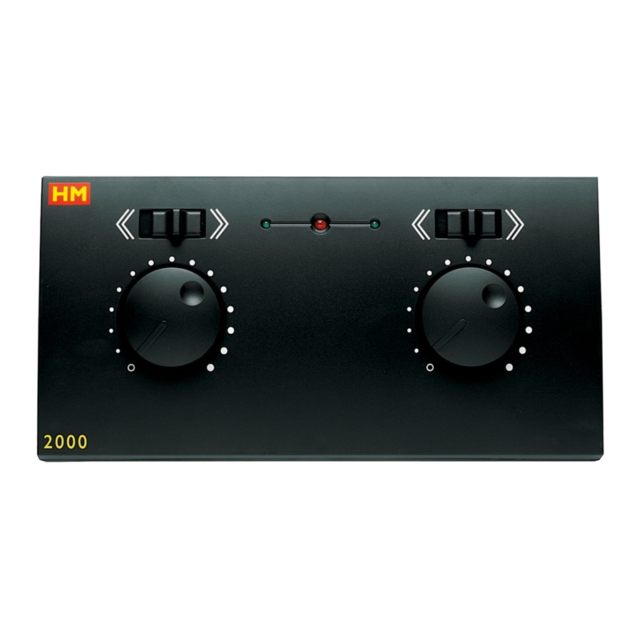
HM 2000+ dC CONTROLLER R8013 & 8013A
(not supplied with HM 2000)
HAMMANT and MORGAN CONTROL
HM 2000+ DC Controllers can only be used as "plug-in" additions to HM 2000 Power Controllers, from which
they take their power supply. The units are produced in left or right-hand versions and can only be connected to
their correct side of the main HM 2000 Power Controller unit. Connect by engaging the appropriate male and
female "D" connectors.
The HM 2000+ then provides another controlled DC output from its rear terminals.
R8013 left-hand
An additional HM 2000+ DC Controller connected to the main unit shares the same secondary winding as the
controlled channel on that side of the main unit to which it is connected.
Therefore HM 2000+ DC Controllers are not isolated from the main unit controlled output to which they are
connected.
In order that the available current is shared efficiently, HM 2000+ DC Controllers should be added to alternate
sides rather than all to the same side.
The "Safety Notes" on page 3 overleaf apply also to HM 2000+ DC Controllers.
Hornby Hobbies Limited guarantee free of charge replacement of defective components within the products'
lives, to include replacement parts subject to availability, labour and return postage to the purchaser.
Any unauthorised repair will invalidate this guarantee.
THIS GUARANTEE DOES NOT AFFECT YOUR STATUTORY RIGHTS.
Telephone: 01843 233525
email: customercare@hornby.com www.hornby.com
Hornby Hobbies Limited, Westwood, Margate, Kent CT9 4JX, United Kingdom
4/821D
0106
R8013A right-hand
Guarantee
Hornby Helpline
Fax: 01843 233527
Page 4
HM 2000 POWER CONTROLLER R8012
HAMMANT and MORGAN CONTROL
The 23VA transformer has three independent, secondary windings, two of which provide the two isolated,
pulsed DC, controlled outputs for train operation. The third isolated output supplies the AC and DC Auxiliary
outputs for the operation of remote controlled points and other accessories.
Each separate output winding is protected by a polyswitch safety cut-out which will shut down the individual
outputs under overheating or short circuit conditions. The transformer is ultimately protected by an internal
thermal fuse which will destruct in an extreme overheating situation.
The controlled DC outputs have variable power control, providing compensation for varying loads and have a
maximum current capacity of 530mA each. The AC and DC auxiliary outputs share a maximum current capacity
of 300mA.
The scope of the HM 2000 Power Controller can be further increased by the addition of left-hand and right-
hand HM 2000+ DC Controllers which are powered by the main unit via the side mounted "D" connectors.
These must be purchased separately as required. In most normal applications, one each of the HM 2000+
DC Controllers can be added, with further additions dependent upon the total current demand of the individual
railway layout. When ordering HM 2000+ units, make sure you specify whether left-hand or right-hand units
are required.
See instructions for HM2000+ DC Controllers on page 4 of this leaflet.
The power supply cable supplied, is fitted with a 3 amp fused plug. If you need to replace the plug, cut the plug
from the cable and dispose of it carefully.
WARNiNG – sHOCK HAZARd. Never insert a cut off plug into a wall socket as electric shock can
occur.
As the colours of the wires in the mains lead of this appliance may not correspond with the coloured markings
identifying the terminals of your plug, proceed as follows:
• Connect the wire coloured green and yellow to the terminal of the plug which is marked with the letter E or
by the earth symbol, or coloured green or green and yellow.
• Connect the wire coloured blue to the terminal of the plug which is marked with the letter N, or coloured
black.
• Connect the wire coloured brown to the terminal which is marked with the letter L, or coloured red.
If it becomes necessary to replace the fuse, only use a 3 amp, BS1362 approved fuse, fitted in the correct fuse
carrier.
The plug should never be used without a fuse carrier of the correct type and colour being fitted. Replacement
fuse carriers can be obtained from Hornby Hobbies Limited or from Official Hornby Service Dealers.
Printed in China
WARNiNG – THis APPLiANCE MusT bE EARTHEd
12V
Advertisement
Table of Contents

Related Manuals for Hornby HM 2000


Summary of Contents for Hornby HM 2000
- Page 1 R8013A right-hand of 300mA. The scope of the HM 2000 Power Controller can be further increased by the addition of left-hand and right- hand HM 2000+ DC Controllers which are powered by the main unit via the side mounted “D” connectors.
- Page 2 3. Auxiliary AC 300mA – maximum output terminals. Brighten as power increases. and output wires. In the event of damage to the power supply cable, please replace with a Hornby 4. Auxiliary DC shared (see note 2) recommended cable. This can be obtained from your Hornby Service Dealer. If any part of the Power Channel “ON/OFF”...
- Page 3 Un contrôleur CC HM 2000+ supplémentaire, connecté à l’unité principale, partage le même bobinage secondaire que le canal Por lo tanto, los controladores de CC HM 2000+ no están aislados de la salida controlada de la unidad principal a la que están contrôlé...
- Page 4 Gefahr eines zufälligen Zusammenschlusses bestehen könnte. Die “D”-Steckverbinder übertragen den 16-Volt Kanal 2 Regelbare Ausgangsstromklemmen AC-Hilfsstrom-Ausgangsklemmen Strom zwischen den HM 2000 und HM 2000+ Geräten; deshalb sollte niemals der Versuch unternommen werden, zwei HM 2000 Netztransformatoren entweder direkt oder über einen HM 2000+ Gleichstromregler (DC) miteinander zu verbinden.
Need help?
Do you have a question about the HM 2000 and is the answer not in the manual?
Questions and answers