
Summary of Contents for B-I Inductrial BI-SM2004
- Page 1 SMOKE DENSITY INDICATOR MODEL : BI-SM2004 B-I INDUSTRIAL CO., LTD. OFFICE : 3F, OSAN B/D, 237-3, HANGNAG-RO 1 GA, YONGSAN-GU, SEOUL, KOREA TEL : (82-2) 795-3077 (REP) FAX : (82-2) 795-3076 Http://www.b-i.co.kr E-mail : bi@b-i.co.kr...
-
Page 2: Table Of Contents
B-I INDUSTRIAL CO., LTD. SMOKE DENSITY INDICATOR REVISION RECORD Description Of Change Pages Table of contents --------------------------------------------------------- 3~4 BI-SM2004 Information ---------------------------------------------- 5~6 Introduction --------------------------------------------------------------------- 7 General Information ------------------------------------------------------ 7 Specifications ------------------------------------------------------------------- 8 Operation --------------------------------------------------------------------- 9~17 Installation ----------------------------------------------------------------- 18~22 Electrical connections... -
Page 3: Table Of Contents
3-1 Preliminary Instructions…………………….……..………………………......18 3-2 Installation - Projector & Receiver Units 3-2-1 General…………………………..…………………………….……….......19 Typical Installation…………………..…………………………………….…....19 3-2-2 Location…………………………..…………………………..........19 3-2-3 Temperature………………………..………………............19 3-2-4 Accessibility………………………..…………………............19 3-2-5 Scanning Distance………………………..……………………...........20 3-2-6 Stratification………………………..……………………............20 3-2-7 suunight………………………………………..............20 3-2-8 Mounting Optical Units………………..…………………..........21 3-2-9 Positive Pressure Application………………………….……………………......22 3-2-10 sealing air…………………………..………………………..........22 BI-SM2004.doc 3/34... - Page 4 Disclose, Type (A).….…………..………………..……………………......26 Inside Installation, Type (B)……………………..………………………......27 5-1-3 Projector And Receiver assembly………………….…..………………......28 5-1-4 Stack and intermediate adaptor..………………….……………………………....29 5-1-5 Smoke Stack Installation……..……………………..…..…………………….....30 5-1-6 Sensor assembly……………………………….…..……………………………….....31 5-1-7 Wiring Diagram Power Source…….………...……………….….……………………………......32 Connection Dia. For Control Panel………….……………………...………......33 List of spare part…………….……………………………………………………………..34 BI-SM2004.doc 4/34...
-
Page 5: Bi-Sm2004 Information
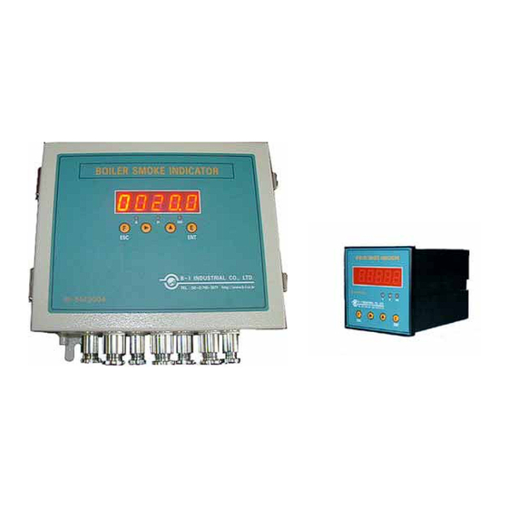
BI-SM2004 Information 1-1-1 General View SMOKE DENSITY INDICATOR Model No. BI-SM2004 Control Panel for Disclose Type Projector Receiver Intermediate Adaptor Stack Adaptor The Unit has been designed to enable Industry to comply with the Clean Air Act and worldwide ships to comply with Canadian Shipping Air Pollution CRC, Vol. -
Page 6: Technical Specification
1-1-2 Technical Specification Technical Specification Model: BI-SM2004 Measuring Range 0.0% - 100% Smoke Density for Black & White Smoke Power Supply AC110 & AC 220 to 240 V, 50/60Hz Dimension of Control Panel 290mm x 240mm x 120mm for Disclose Type Weight of Control Panel 5.5kgs... -
Page 7: Introduction
B-I INDUSTRIAL CO., LTD. SMOKE DENSITY INDICATOR 1-2 INTRODUCTION The environments is high on the political agenda at the moment and Pollution is still very much a live issue. Accordingly, we have developed this system to meet requirements for the Air Pollution Control Act, etc enable to measure and acknowledge the quantity of gas emitted in order for the prompt response against the status of smoke. -
Page 8: Specifications
115 mm x 49 mm x 12Ø X 4 HOLE Mounting Tube : Optional Extra Inject air connection : 10mm BSP Standard Connection 0.5 BAR Max. Temperature : Weight : Projector 0.4Kg, Receiver 0.4Kg Miniclean Adapter 2.3Kg, Stack Adapter 2.1Kg BI-SM2004.doc 8/34... -
Page 9: Operation
The Smoke Density Indicator enters its warm-up, this takes approximately 60 seconds to complete. During warm-up the following screens appear on the display. START WARM-UP DISPLAY THE SOFTWARE VERSION CHECKING SMOKE SENSOR COMPLETED WARM-UP AND NORMAL OPERATING DISPLAY BI-SM2004.doc 9/34... -
Page 10: Setting Value
☞. When Setting 4-20mA if you push button simultaneously, the value is decreased. 2-1-2 Setting Value You can configure below value by means of using above 4 buttons. Factory default setting ALARM : HIGH LEVEL : HIGH HIGH LEVEL : BI-SM2004.doc 10/34... -
Page 11: Installation
If you press for 5 seconds, Setup Menu is displayed. By means of button, you can move to another menu. The sequence of Setup menu display is as follows: You can start to set up, if you press button BI-SM2004.doc 11/34... -
Page 12: Alarm
☞. Alarm Setting Press , Displayed ALARM value Pressing button, Adjust ALARM value(0~100%) Press , Diplayed Completed Alarm setup ☞. High Level Setting Press , Displayed HIGH value Pressing button, Adjust HIGH value(0~100%) Press , Diplayed Completed High level setup BI-SM2004.doc 12/34... -
Page 13: High High Level
, Displayed HIGH HIGH value Pressing button, Adjust HIGH HIGH value(0~100%) Press , Diplayed Completed High High level setup ☞. Delay Time Setting Press , Displayed DELAY TIME Pressing button, Adjust DELAY TIME (0~60sec.) Press , Diplayed Completed Delay Time setup BI-SM2004.doc 13/34... -
Page 14: Filter
☞. Span Setting : Zero Press , Displayed Zero & Reading AD value AD Value become steady (about 2 min. Later), Press , Displayed Completed Zero Setup. And Light Beam will be switched off and converted to Span 100% Setting Mode. BI-SM2004.doc 14/34... -
Page 15: 4-20Ma
Press , Displayed 4mA & Reading AD value By Press button, Adjust the AD value until Ampere Meter read out 4mA Press , Displayed Completed 4mA Signal Output setup, and dissplay converts to 20mA Setting Mode. BI-SM2004.doc 15/34... - Page 16 Completed 20mA Signal Output setup CAUTION ※※※ ※※※ Please note that 4-20mA is factory default thus re-setting is not necessary and it should not be changed by users. If the re-setting is to be indispensable, please contact our Technical Department. BI-SM2004.doc 16/34...
-
Page 17: Trouble Shooting
20p cable damaged Replace 20p cable with new one Zero resetting & calibration Sensor fail 100% span resetting & calibration Abnormal Glass was dirty Cleaned glass indication Cleaned stack adaptor Stack adaptor is Clogged Check sealing air line BI-SM2004.doc 17/34... -
Page 18: Preliminary Instructions
Max. temperature 70°C. B.3 Prevent external light sources affecting the optics i.e. install away from duct or flue exit. B.4 The optical units should be installed after possible pipe connection to an inert gas system. BI-SM2004.doc 18/34... -
Page 19: Installation - Projector & Receiver Units
Normally sufficient cooling effect is provided by air purging. The temperature of the Projector / Receiver units should not exceed 70°C. 3-2-4 Accessibility Optical units must be located such that they are readily accessible for lens cleaning, routine maintenance and servicing. BI-SM2004.doc 19/34... -
Page 20: Scanning Distance
Mounting tubes are normally supplied and fitted by the steel fabricator and must always be installed in the horizontal plane. The mounting tubes should be fabricated from 50A, Schedule 80 pipe and special flange O.D 115 mm X I.D 50mm X 15T BI-SM2004.doc 20/34... - Page 21 S M O K E S T A C K 4 0 A P IP E P R O J E C T O R R E C E IV E R S T A C K A D A P T O R BI-SM2004.doc 21/34...
-
Page 22: Positive Pressure Application
B-I INDUSTRIAL CO., LTD. SMOKE DENSITY INDICATOR 3-2-9 Positive Pressure Applications On oil fired boilers a pressure wave may be caused when the burner ignites disturbing soot accumulations and depositing them on the lenses. Therefore, the units should be located as far as possible from the actual flue gas outlet of the boiler. -
Page 23: Electrical Connections
Cable shields to be grounded only at control unit. Maximum cable length is governed by the total loop resistance of the core and should not exceed the following limits: Projector: 5 Ohms Receiver: 25 Ohms 4-20mA Analogue Output: 25 Ohms Wiring Diagram BI-SM2004.doc 23/34... -
Page 24: Mains Connection
4-1-2 Main Connection The unit is normally supplied for 220V, 60Hz operation and, optionally, 110V, 60 Hz. For optimum performance the mains supply to the BI-SM2004 should never be interrupted. 4-1-3 Alarm Relays Alarm relays are rated at 5 Amps 250 V.A.C. non-inductive load and provide non-committed change-over contacts for external circuits. -
Page 25: Installation Drawing
BI-SM2004.doc 25/34... -
Page 26: Contorl Panel Dimension Disclose, Type (A)
BI-SM2004.doc 26/34... -
Page 27: Inside Installation, Type (B)
BI-SM2004.doc 27/34... -
Page 28: Projector And Receiver Assembly
BI-SM2004.doc 28/34... -
Page 31: Sensor Assembly
BI-SM2004.doc 31/34... -
Page 32: Wiring Diagram Power Source
BI-SM2004.doc 32/34... -
Page 33: Connection Dia. For Control Panel
BI-SM2004.doc 33/34... -
Page 34: List Of Spare Part
BI-SM2004.doc 34/34...
Need help?
Do you have a question about the BI-SM2004 and is the answer not in the manual?
Questions and answers