Table of Contents
Advertisement
Quick Links
BOCK HG
Assembly instructions
09652-06.2021-Gb
Translation of the original instructions
HG(X)12P/60-4 S
HG(X)12P/75-4 (S)
HG(X)12P/90-4 (S)
HG(X)12P/110-4 (S)
HGX12P/75 ML 1 LG
HGX12P/90 ML 2 LG
HGX12P/110 ML 2 LG
BOCK
®
12
P (HC/LG)
HG12P/60-4 S HC
HG12P/75-4 (S) HC
HG12P/90-4 (S) HC
HG12P/110-4 (S) HC
HGX12P/60 S 0,7 LG
HGX12P/75 S 1 LG
HGX12P/90 S 2 LG
HGX12P/110 S 3 LG
colour the world
of tomorrow
Advertisement
Table of Contents

Subscribe to Our Youtube Channel
Related Manuals for BOCK BOCK HG12P


Summary of Contents for BOCK BOCK HG12P
- Page 1 BOCK HG P (HC/LG) Assembly instructions 09652-06.2021-Gb Translation of the original instructions HG(X)12P/60-4 S HG12P/60-4 S HC HG(X)12P/75-4 (S) HG12P/75-4 (S) HC HG(X)12P/90-4 (S) HG12P/90-4 (S) HC HG(X)12P/110-4 (S) HG12P/110-4 (S) HC HGX12P/60 S 0,7 LG HGX12P/75 ML 1 LG...
-
Page 2: Table Of Contents
Observe the safety instructions contained in these instructions. These instructions must be passed onto the end customer along with the unit in which the compres- sor is installed. Manufacturer Bock GmbH 72636 Frickenhausen Contact Bock GmbH Benzstraße 7... - Page 3 Contents Page Areas of application 4.1 Refrigerants 4.2 Oil charge 4.3 Limits of application Areas of application on HC and LG compressors 5.1 Refrigerants 5.2 Oil charge 5.3 Limits of application Compressor assembly 6.1 Storage and transport 6.2 Setting up 6.3 Pipe connections 6.4 Pipes 6.5 Laying suction and pressure lines 6.6 Suction pipe filter and filter drier 6.7 Operating the shut-off valves 6.8 Operating mode of the lockable service connections...
-
Page 4: Safety
1| Safety 1.1 Identification of safety instructions: DANGER Indicates a dangerous situation which, if not avoided, will cause immediate fatal or serious injury. WARNING Indicates a dangerous situation which, if not avoided, may cause fatal or serious injury. CAUTION Indicates a dangerous situation which, if not avoided, may cause fairly severe or minor injury. ATTENTION Indicates a situation which, if not avoided, may cause property damage. INFO Important information or tips on simplifying work. 1.2 Qualifications required of personnel WARNING Inadequately qualified personnel poses the risk of accidents, the consequence being serious or fatal injury. Work on compressors is therefore reserved for personnel which is qualified to work on pressurized refrigerant systems: • For example, a refrigeration technician, refrigeration mechatronic engineer. As well as professions with comparable training, which enables personnel to assemble, install, maintain and repair refrigeration and air-conditioning systems. -
Page 5: General Safety Instructions
These assembly instructions describe the standard version of the compressor named in the title manufactured by Bock. Bock refrigerating compressors are intended for installation in a machine (within the EU according to the EU Directives 2006/42/EC Machinery Directive and 2014/68/EU Pres- sure Equipment Directive). -
Page 6: Safety Instructions For Use Of Flammable Refrigerants
2 | Safety instructions for use of flammable refrigerants 2.1 Safety instructions DANGER • Explosion and fire risk! Hydrocarbons and synthetic HFO refrigerants are colourless, combustible gases which occur naturally and which are explosive in a certain blend! • Hydrocarbons are classified into the safety group A3 (highly- inflammable refrigerant) according to EN 378. -
Page 7: Product Description
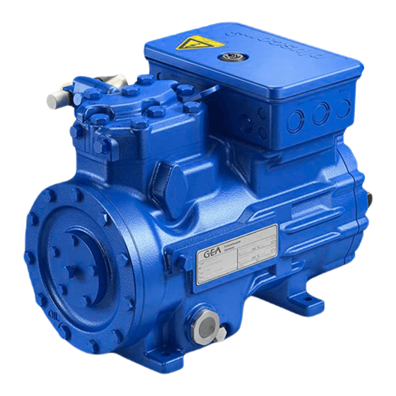
3| Product description 3.1 Short description • Semi-hermetic two-cylinder reciprocating compressor with oil pump lubrication. • Suction gas cooled drive motor. Transport eyelet Valve plate Name plate Oil pump Oil sight glass Fig. 1 Cylinder cover Discharge shut-off valve Terminal box Drive section Suction shut-off valve... -
Page 8: Type Key Lg Compressors
3| Product description Typschild (Beispiel) 3.2 Name plate (example) BOCK Bock GmbH, Benzstr. 7 72636 Frickenhausen, Germany HGX12P/110-4S AS35830A001 AS35830A001 10,6/6,1A 11,3 BOCK lub E55 Fig. 3 Typbezeichnung Spannung, Schaltung, Frequenz Type designation Voltage, circuit, frequency 50 Hz Maschinennummer Nenndrehzahl 50 Hz Machine number Nominal rotation speed... - Page 9 3| Product description 3.4 Type key HC compressor (example) 110- Hydrocarbons Motor variant ³ Number of poles Swept volume ² Numbers of cylinders Size Series ¹ ¹ HG - Hermetic Gas-Cooled (suction gas-cooled) ² ) Additional declaration for Pluscom compressors ³ S - More powerful motor 3.5 Typ key LG compressor (example) HFO refrigerant Engine performance in hp...
-
Page 10: Areas Of Application
4.2 Oil charge The compressors are filled at the factory with the following oil type: BOCK lub E55 - for R404A/R507 - for R22 BOCK lub A 46 Compressors with ester oil charge ( BOCK lub E55 ) are marked with an X in the type designation (e.g. HGX12P/110-4). INFO For refilling, we recommend the above oil types. Alternatives: see chapter 9.4 ATTENTION The oil level must be in the max. -
Page 11: Areas Of Application On Hc And Lg Compressors
• LG compressors: BOCK lub E55 BOCK lub E85 (from t > 15°C, must be specified in the order) 5.3 Operating limits ATTENTION Compressor operation is possible within the operating limits. These can be found in Bock compressor selection tool (VAP) under vap.bock.de. Observe the information given there and the follo- wing notes: - Minimum superheating ∆t = 20 K (only at HC compressors) In order to guarantee the required minimum superheating of ∆t = 20 K, an internal heat exchanger IHX may have to be installed. (only at HC compressors) - Min. pressure gas temperature ≥ 50°C (min. 20K over condens- ing temperature). -
Page 12: Compressor Assembly
6| Compressor assembly INFO New compressors are factory-filled with inert gas. Leave this ser- vice charge in the compressor for as long as possible and prevent the ingress of air. Check the compressor for transport damage before starting any work. 6.1 Storage and transport Storage at (-30 °C) - (+70 °C), maximum permissible relative humidi- ty 10 % - 95 %, no condensation Do not store in a corrosive, dusty, vaporous atmosphere or in a com- bustible environment. -
Page 13: Pipes
6| Compressor assembly The pipe connections have graduated inside diameters so that pipes with standart millimetre and inch dimensions can be used. The connection diameters of the shut-off valves are rated for maximum compressor output. The actual required pipe cross section must be matched to the output. The same applies for non-return valves. Fig. 5: graduated internal diameter 6.4 Pipes Pipes and system components must be clean and dry inside and free of scale, swarf and layers of rust and phosphate. -
Page 14: Operating The Shut-Off Valves
6| Compressor assembly 6.7 Operating the shut-off valves Before opening or closing the shut-off valve, release the valve spindle seal by approx. of a turn counter-clockwise. After activating the shut-off valve, re-tighten the adjustable valve spindle seal clockwise. Tighten Release Valve spindle seal Fig. 7 Fig. -
Page 15: Electrical Connection
7| Electrical connection DANGER Risk of electric shock! High voltage! Only carry out work when the electrical system is disconnected from the power supply! ATTENTION When attaching accessories with an electrical cable, a minimum bending radius of 3 x the cable diameter must be maintained for laying the cable. INFO Connect the compressor motor in accordance with the circuit diagram (see inside of terminal box). Use suitable cable entry point of the correct protection type (see name plate) for routing cables into the terminal box. Insert the strain reliefs and prevent chafe marks on the cables. - Page 16 7.3 Circuit diagramm for direct start 230 V ∆ / 400 V Y FC1.1 I> I> I> FC1.1 L3 N PE -EC1 Θ B1 B2 INT69G Compressor terminal box Anschlußkasten Verdichter Fig. 11 Cold conductor (PTC sensor) motor winding Thermal protection thermostat (PTC sensor) Load circuit safety switches Control power circuit fuse High pressure safety monitor Safety chain (high/low pressure monitoring ) Release switch (thermostat)
- Page 17 L1.1 L2.1 L3.1 L1.2 P> Θ Θ DANGER Explosion risk! Electronic trigger INT69 G at HC and LG compressors has to be installed outside any danger area! See also chapter 7.7. Main switch Control voltage switch Compressor motor Compressor contactor INT69 G Electronic trigger unit INT69 G Oil sump heater...
-
Page 18: Electronic Trigger Unit Int69 G
7| Electrical connection 7.4 Electronic trigger unit INT69 G The compressor motor is fitted with cold conductor temperature sensors (PTC) connected to the electronic trigger unit INT69 G in the terminal box. In case of excess temperature in the motor winding, the INT69 G deactivates the motor contactor. Once cooled, it can be restarted only if the electronic lock of the output relay (terminals B1+B2) is released by interrupting the supply voltage. - Page 19 7| Electrical connection 7.6 Function test of the trigger unit INT69 G Before commissioning, after troubleshooting or making changes to the control power circuit, check the functionality of the trigger unit. Perform this check using a continuity tester or gauge. Relay position INT69 G Gauge state Relay position Deactivated state 11-12 INT69 G switch-on 11-14...
-
Page 20: Oil Sump Heater On Hc And Lg Compressors
7 | Electrical connection 7.8 Oil sump heater at HC and LG compressors As the solubility of hydrocarbons and HFO refrigerants in oil can be very high, especially at high suction pressures, the compressor must be equipped with an oil sump heater. For this reason, a pump-down circuit is recommended during standstill to reduce the suction-side standstill pressures. ATTENTION The oil sump heater must generally be connected and operated! • In a TT- or TN system, a residual current protection device (RCD) must be used. -
Page 21: Preparations For Start-Up
8| Commissioning 8.1 Preparations for start-up INFO To protect the compressor against inadmissible operating conditions, high pressure and low pressure pressostats are mandatory on the installation side. The compressor has undergone trials in the factory and all functions have been tested. There are therefore no special running-in instructions. Check the compressor for transport damage! 8.2 Pressure strength test The compressor has been tested in the factory for pressure integrity. If however the entire system is to be subjected to a pressure integrity test, this should be carried out in accordance with EN 378-2 or a corresponding safety standard without the inclusion of the compressor. -
Page 22: Refrigerant Charge
8| Commissioning 8.5 Refrigerant charge CAUTION Wear personal protective clothing such as goggles and protective gloves! Make sure that the suction and pressure line shut-off valves are open. With the compressor switched off, add the liquid refrigerant directly to the condenser or receiver, breaking the vacuum. If the refrigerant needs topping up after starting the compressor, it can be topped up in vapour form on the suction side, or, taking suitable precautions, also in liquid form at the inlet to the evaporator. -
Page 23: Connection Of Oil Level Regulator
Annual checks: Oil level, leak tightness, running noises, pressures, temperatures, function of auxiliary devices such as oil sump heater, pressure switch. 9.3 Spare parts recommendation/accessories Available spare parts and accessories can be found on our compressor selection tool under vap.bock.de as well as at bockshop.bock.de. Only use genuine Bock spare parts! -
Page 24: Lubricants / Oil
It is for this reason, that we only recommend the use of oil from Bock! Bock assumes no liability for any damage arising from alternative oil types. -
Page 25: Technical Data
10| Technical data Sound pressure level Oil charge (sight glass centre) Oil charge (ex works) Suction line Discharge line Weight Starting current (rotor locked) Max. power consumption Max. operating current 220-240 V ∆ / 380-420 V Y - 3 - 50 Hz Voltage 265-290 V ∆ / 440-480 V Y - 3 - 60 Hz Displacement (1450 / 1740 rpm) No. of cylinders... -
Page 26: Dimensions And Connections
über / above prohibited. Offenders will be held liable for the payment of damages. All rights reserved in the event 1000 1 / 4 “ NPTF BOCK Gm Zust. / Rev. Maß / Dimension Passung / Clearance Änd.-Nr. / Mod-No. -
Page 27: Declaration Of Incorporation
12| Declaration of incorporation Declaration of incorporation for incomplete machinery in accordance with EC Machinery Directive 2006/42/EC, Annex II 1. B Manufacturer: Bock GmbH Benzstraße 7 72636 Frickenhausen, Germany We, as manufacturer, declare in sole responsibility that the incomplete machinery... -
Page 28: Service
13| Service Dear customer, if you have any questions about installation, operation and accessories, please contact our technical service or specialist wholesaler and/or our representative. The Bock service team can be contacted by phone, +49 (0)7022 9454-0 or via service@bock.de Yours faithfully Bock GmbH... - Page 30 BOCK ® Bock GmbH Benzstraße 7 72636 Frickenhausen Germany Phone +49 7022 9454-0 +49 7022 9454-137 www.bock.de © Bock GmbH. All rights reserved. Subject to modifications. Printed in Germany.
Need help?
Do you have a question about the BOCK HG12P and is the answer not in the manual?
Questions and answers