Table of Contents
Advertisement
Advertisement
Table of Contents

Subscribe to Our Youtube Channel
Related Manuals for Hoymiles DTU-MI-GPRS


Summary of Contents for Hoymiles DTU-MI-GPRS
- Page 1 Version D-4-1.0 @2019...
-
Page 2: Table Of Contents
6. Site creation on HMP ............................16 7. Customer Login ..............................17 8. Browse the Web Station ............................. 17 9. View Phone APP..............................18 10. Troubleshooting ..............................18 11. Datasheet ................................19 © 2019 Hoymiles Converter Technology Co., Ltd. All rights reserved. -
Page 3: Important Safety Information
Please read all instructions and warnings on the technical specifications carefully. Do not use Hoymiles products in a way that is not suggested by manufacture. If doing so, it may cause death or injury to persons or damage to equipment. -
Page 4: Other Information
Microinverter industry. 2.2 DTU The DTU is the critical component in Hoymiles microinverter system. It works as the communication gateway, which operates between the Hoymiles microinverters and the Hoymiles Monitoring Server. The DTU communicates with the microinverter wirelessly via 2.4G RF, collecting the operation data of the system. -
Page 5: Introduction To Dtu Interface
A computer will be needed to connect to the same network with DTU, then open the DTU local interface in the browser by entering the IP address shown on the LCD screen. © 2019 Hoymiles Converter Technology Co., Ltd. All rights reserved. -
Page 6: Dtu Home Interface
3.4 DTU View Interface There are three options under “View” bottom: DTU Information; System Inventory; RF Information. © 2019 Hoymiles Converter Technology Co., Ltd. All rights reserved. - Page 7 (3) RF Information: indicates the basic information of the DTU communication module, including software and hardware versions of the DTU module in the system, as well as the module ID and status. © 2019 Hoymiles Converter Technology Co., Ltd. All rights reserved.
-
Page 8: Configuration Interface
Click the “GFDI Fault” under the “Configuration” to open the ground fault manage interface. If there is a ground fault, it will list on this page (as the picture shows below). It can be cleared by clicking the “Clear Fault” bottom. If the problem persists, please contact Hoymiles technical support team. - Page 9 After inputting all of the microinverters’ IDs and repeater’s ID, please click the “Reg ID” to finish registration. All details system operating information will be listed on the Home interface. © 2019 Hoymiles Converter Technology Co., Ltd. All rights reserved.
-
Page 10: Dtu Installation
The temperature should be between -20ºC and 55ºC. If you plan to install the DTU on the wall, two #8 (4.166mm diameter) screws and a screwdriver shall be prepared in advance. © 2019 Hoymiles Converter Technology Co., Ltd. All rights reserved. -
Page 11: Dimensions
2. Locate the DTU 7. Add Microinverter ID 8. Check the Communication 3. Connect to the Internet between Microinverters and DTU 4. Start procedure 9. Wall-mount the DTU (optional) 5. Normal operation © 2019 Hoymiles Converter Technology Co., Ltd. All rights reserved. -
Page 12: Install The Dtu
Please follow the related manual to install the PV modules and the microinverters. 4.52 Locate the DTU The communication distance of Hoymiles DTU is 150m in the open space. However, in the real installation, the environment may be more complex. It may have some obstacles like walls or roofs, which will reduce the communication distance. - Page 13 When the DTU is powered on, it goes through the initial boot sequence. During this sequence, the DTU LCD screen displays start-up progress as shown: BOOT SYS setup 10:26:30 System setup… 10:27:55 ETH_BSP_Config 10:27:55 IP: 0.0.0.0 © 2019 Hoymiles Converter Technology Co., Ltd. All rights reserved.
- Page 14 Add all microinverters’ IDs by auto mode or manual mode, referring to “Devices ID Interface” on page 9-11. 4.58 Check the Communication between Microinverters and DTU a. There are two methods to check the communication between microinverters and DTU: © 2019 Hoymiles Converter Technology Co., Ltd. All rights reserved.
- Page 15 100mm. The maximum screw head diameter is 0.35”, a #8 screw is recommended. Step 3. Slide the DTU onto the mounting screws, aligning the DTU screw holes with the screws installed in step 2. © 2019 Hoymiles Converter Technology Co., Ltd. All rights reserved.
-
Page 16: Complete Installation Map
Complete system information of the installation map shown as follows. 6. Site creation on HMP a. Install Hoymiles Installer APP by searching “Hoymiles” at App Store (IOS) or Play Store (Android). b. Open the APP and login in with your installer account name and password. If you are a... -
Page 17: Customer Login
Please wait about 30 minutes, the station will show online, and all the MI-IDs are detected. 7. Customer Login a. Please download the End User App. You can search “Hoymiles” at the App Store (IOS) or Play Store (Android). -
Page 18: View Phone App
Relocate the DTU to ensure that the DTU reception range can cover all microinverters in the system. If this problem occurs only on the cloudy day, try again during the better weather condition. © 2019 Hoymiles Converter Technology Co., Ltd. All rights reserved. -
Page 19: Datasheet
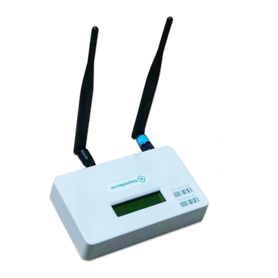
-20° C to 55° C Dimensions(W×H×D) 149mm×90mm×31mm Weight 0.22 kG Mounting system Wall mounting Display 16 Characters x 2 lines LCD Features Compliance IEC60950 IEC61000-6-2 FCC Part15 Class B / Class C © 2019 Hoymiles Converter Technology Co., Ltd. All rights reserved.
Need help?
Do you have a question about the DTU-MI-GPRS and is the answer not in the manual?
Questions and answers