Table of Contents
Advertisement
Advertisement
Table of Contents

Subscribe to Our Youtube Channel
Related Manuals for Hoymiles DTU-MI


Summary of Contents for Hoymiles DTU-MI
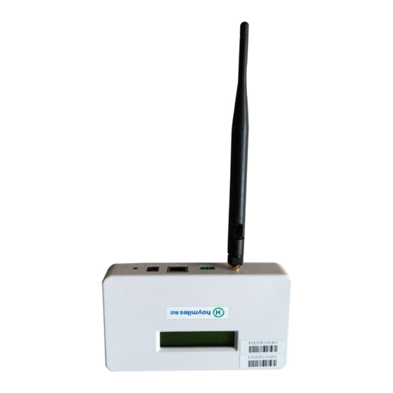
- Page 1 DTU-MI User Manual Data Transfer Unit (model: DTU-MI)
-
Page 2: Table Of Contents
Important Safety Information ..................... 2 Read this First ........................2 Safety Instructions ......................2 User ........................... 2 The Hoymiles Microinterver System ..................3 Basic DTU Operation ........................ 4 LCD Screen Display at Start Up ..................4 Normal Operation....................... 5 DTU Local Interface ......................6 DTU Home Interface ...................... -
Page 3: Important Safety Information
DTU-MI Important Safety Information Read this First This manual includes important instructions for installing and maintaining the Hoymiles data transfer unit(DTU-MI). Safety Instructions Note that only professionals can install or replace DTU. Don't try to repair DTU because it contains parts that are not available to users. If DTU is damaged, please send the DTU back to our dealer for repair. -
Page 4: The Hoymiles Microinterver System
PV panels and the operation data of the microinverters to the DTU, which is the hardware basis of the panel-level monitoring. With efficiency up to 96.7% and MPPT efficiency up to 99.9%, Hoymiles microinverters rank in the first level around the world. -
Page 5: Basic Dtu Operation
DTU-MI Basic DTU Operation LCD Screen Display at Start Up When the DTU starts up, it goes through the initial boot sequence. During this sequence, the DTU LCD screen displays start-up progress as shown: BOOT SYS setup 10:26:30 System setup…... -
Page 6: Normal Operation
DTU-MI Normal Operation When the DTU completes the start up process and obtains the IP address, normal operation begins. During the normal operation, the LCD screen displays the basic operation status of the system, and the two screens shown as below alternate all the time.(screens 1 and 2 will appear when you configure the Internet access). -
Page 7: Dtu Local Interface
DTU-MI DTU Local Interface The DTU has an embedded web server, which enables you to view the operation data and status of the system, manage the devices and clear fault locally via a browser. You need to get your computer connected to the same network with DTU to open the DTU local interface in your browser by entering the IP address shown on the LCD screen. -
Page 8: View Project
DTU-MI View Project Click “ View ”, appear three options. (1) ViewDTU Information, access to the DTU basic information interface, which contains the following information: www.hoymiles.com... - Page 9 Client Set item include server address, server IP, server port. Server address: data4.hoymiles.com, Factory settings Server IP: 119.3.25.186, Factory settings Dest Port: 10017, Factory settings (2) ViewSystem Inventory, check the software and hardware version number of the microinverter in the system.
-
Page 10: Ground Fault Reset
DTU-MI Ground Fault Reset Click “ConfigurationGFDI Fault” to open ground fault manage interface. You can check whether the microinverters have a ground fault or not. If the faults exist, click “Clear Fault”. If the problem persists, please contact our technical support. -
Page 11: Device Id Management
DTU-MI Device ID Management During the first-time installation or maintenance of DTU, you need to add or delete the microinverters’ IDs to realize the monitoring of whole system. (1) Manual Config Click “Device IDManual Config”to open manual ID manage interface. - Page 12 DTU-MI You need add the IDs into the blank box shown below manually, and then click “Add ID”. After inputting all of the microinverters’ IDs, you need to click “Reg ID” to finish registration. Then you can see the detailed operating information of system in the Home interface.
-
Page 13: Dtu Installation
DTU-MI (2) Auto Scan Click ”Device IDAuto Scan” to open the auto ID management interface. Click “Scan ID” to start automatic search for microinverters. When the DTU detects all the microinverters’ IDs, you need to click “Reg ID” to finish registration. If the DTU cannot detect all the microinverters in the system over 30 minutes, please use manual mode instead. -
Page 14: Installation Sequence
Install the PV modules and the microinverters as directed by the installation manuals. 2. Locate the DTU The communication distance of Hoymiles DTU is 200m in the open space. But in the real installation, the environment may be more complex. It may have some obstacles like walls or roofs, which will reduce the communication distance. - Page 15 DTU-MI Material Relative signal range reductions Wood/Glass 0-10% Stone/Pressed cardboard 10%-40% Reinforced concrete (reduction increases 10%-90% with amount of reinforcement) Metal Up to 100% Therefore, the DTU shall be placed as close to the microinverters as possible at the site to ensure good communication between DTU and microinverters.
- Page 16 DTU-MI Connect to the Internet Use one of two methods described below to connect DTU to a broadband router: ① Ethernet Cable ② Power Line Communication Bridges Ethernet Cable Plug the Ethernet cable into the RJ-45 port on the DTU.
- Page 17 DTU-MI 4. Check the Internet Connection Look for the “YC” indication. ”YC” indicates DTU communicates with the Internet. YC 10:27:55 --XXXX IP: 192.168.1.122 If it still shows “NC” for several minutes after connecting to the broadband router, see “Troubleshooting” on page 20.
- Page 18 DTU-MI 7. Wall Mounting(optional) After the DTU has detected all microinverters of the system, you can mount the DTU on a wall near the site. Mount the DTU in a cool and dry location and avoid heat-generating devices (oven, warmer).
-
Page 19: Complete Installation Map
DTU-MI Complete Installation Map When the system is energized and the DTU detects the microinverters, you need complete the installation map. Peel the serial number label from the DTU and place it on the installation map. Complete system information of the installation map shown as follows. -
Page 20: Browse The Web Station
DTU-MI Browse the Web Station Login your account, browse the web station. View Phone APP Download mobile phone APP and view station information. www.hoymiles.com... -
Page 21: Troubleshooting
DTU-MI Troubleshooting LCD Screen Displays “NC” This means that the DTU has no connection to the remote monitoring server. Check network connectivity to the router. Check whether the router can connect to the Internet or not The Link Number is less than Total Number of Microinverters “LINK: XX”... -
Page 22: Datasheet
DTU-MI Datasheet Model DTU-MI Communication to Microinverter Type 2.4G RF Sample Rate 5-15 minutes Maximum di s tance(free space) 200m 99 ID Maximum number of inverters connected Communication to Router/PC RJ45 Ethernet 10M/100M GPRS Communication GSM four frequency band:850/900/1800/1900MHz Power Supply...
Need help?
Do you have a question about the DTU-MI and is the answer not in the manual?
Questions and answers