
Related Manuals for Bosch Worcester AGS 5


Summary of Contents for Bosch Worcester AGS 5
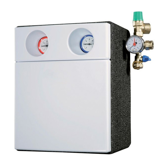
- Page 1 INSTALLATION AND SERVICING INSTRUCTIONS SOLAR PUMP STATIONS AGS 5/5E, AGS 10/10E FOR SEALED SOLAR HEATING SYSTEMS AND INDIRECT FED DOMESTIC HOT WATER...
-
Page 2: Table Of Contents
CONTENTS CONTENTS Safety instructions and explanation Commissioning of symbols Use of heat transfer fluid Purging and filling with a hand pump General safety instructions (air vent on roof) Symbols 6.2.1 Purging the pipes 6.2.2 Carrying out pressure test with water 6.2.3 Replacing water with heat transfer fluid Information about the product... -
Page 3: Safety Instructions And Explanation Of Symbols
SAFETY INSTRUCTIONS AND EXPLANATION OF SYMBOLS SAFETY INSTRUCTIONS AND EXPLANATION OF SYMBOLS EXPLANATION OF SYMBOLS GENERAL SAFETY INSTRUCTIONS WARNINGS ABOUT THIS MANUAL This manual contains important information for the safe Warnings in this document are framed and and correct installation and maintenance of the solar identified by a warning triangle printed pump station. -
Page 4: Information About The Product
INFORMATION ABOUT THE PRODUCT INFORMATION ABOUT THE PRODUCT PRODUCT DESCRIPTION Benchmark places responsibilities on both manufacturers and installers. The purpose is to ensure that customers are provided with the correct equipment for their needs, that it is installed, commissioned and serviced in accordance with the manufacturer’s instructions by competent persons and that it meets the requirements of the appropriate Building Regulations. -
Page 5: Specifications And Variants
INFORMATION ABOUT THE PRODUCT SPECIFICATIONS AND VARIANTS AGS 5 AGS 5E Maximum possible temperature °C Flow: 130 / return: 110 (pump) Safety valve response pressure Safety valve – DN 15, ¾ " connection DN 15, ¾ " connection Mains supply –... -
Page 6: Example Applications
INFORMATION ABOUT THE PRODUCT EXAMPLE APPLICATIONS 7747006489.03-2.SD Fig. 3 Different hydraulic applications Standard system with 2-line solar pump station Two collector arrays (east/west) with 1-line and 2-line solar pump stations Dual-tank system with 1-line and 2-line solar pump stations Standard system with 1-line solar pump station and air vent on roof 6 720 643 603 (2011/11) -
Page 7: Regulations
REGULATIONS REGULATIONS Observe all standards and guidelines applicable to the installation and operation of the system in your country and region. TECHNICAL REGULATIONS APPLICABLE IN THE U.K. FOR THE INSTALLATION OF THERMAL SOLAR HEATING SYSTEMS • Electrical connection: – Current IEE wiring regulations •... -
Page 8: Installing Pipework
INSTALLING PIPEWORK INSTALLING PIPEWORK GENERAL INFORMATION CONNECTING THE PIPES REGARDING PIPEWORK CAUTION: System damage from heat buildup when brazing CAUTION: System damage from plastic B Do not carry out brazing close to pipes (e.g. PE pipes) evacuated tube collectors. B Use only materials which can withstand the temperatures up to 150 °C which B Copper pipes for solar heating systems should always occur in solar heating systems. -
Page 9: Installation Of Solar Pipework
INSTALLING PIPEWORK INSTALLATION OF SOLAR PIPEWORK EARTHING PIPES Work must be carried out by an authorised electrician. B One earthing clamp must be fitted to both the flow pipe and the return pipe (at any position). B Connect the earthing clamps to the building's equipotential bonding strip by means of a standard PVC-sheathed bonding cable (NYM type, at least 6 mm... -
Page 10: Installing The Solar Pump Station
INSTALLING THE SOLAR PUMP STATION INSTALLING THE SOLAR PUMP STATION LAYOUT OF THE INSTALLATION MOUNTING THE SOLAR PUMP SPACE STATION CAUTION: Damage to the solar heating 1-LINE SOLAR PUMP STATION station from pump buildup B Drill a hole (2) and mount the solar pump station B Make sure that the ventilation slots, at using the wall plug and screw supplied. -
Page 11: Installing The Safety Assembly
INSTALLING THE SOLAR PUMP STATION INSTALLING THE SAFETY ASSEMBLY CONNECTING THE PRE-COOLING VESSEL If the pipeline to the expansion vessel needs to be laid For 1-line solar pump station: on a rising incline, an additional air vent must be B Install the safety assembly on the left. installed. -
Page 12: Installing The Expansion Vessel
INSTALLING THE SOLAR PUMP STATION CONNECTING PIPES AND BLOW-OFF 5.5.2 INSTALLING THE EXPANSION VESSEL (AVAILABLE AS AN ACCESSORY) LINE TO THE SOLAR PUMP STATION B Install the expansion vessel with the relevant DANGER: Possible injuries and system mounting materials. damage from incorrectly installed blow-off B Connect the expansion vessel (3) in the return line on line the solar heating station's safety assembly. -
Page 13: Installing The Temperature Sensors
INSTALLING THE SOLAR PUMP STATION INSTALLING THE TEMPERATURE SENSORS Electrical connections must be carried out by authorised electricians. The temperature sensors are protected against polarity reversal. 5.7.1 COLLECTOR TEMPERATURE SENSOR If the collector sensor lead needs to be extended to reach the controller, a waterproof junction must be used at the connections where they are exposed to moisture. -
Page 14: Commissioning
COMMISSIONING COMMISSIONING PURGING AND FILLING WITH A HAND At the time of commissioning, complete all PUMP (AIR VENT ON ROOF) relevant sections of the Benchmark Checklist located on the inside back pages of this 6.2.1 PURGING THE PIPES document. After servicing, complete the relevant Service If a pre-cooling vessel is installed: Interval Record section of the Benchmark B Disconnect the pre-cooling vessel from... -
Page 15: Carrying Out Pressure Test With Water
COMMISSIONING B Close the fill and drain valves (3) in the solar heating 6.2.2 CARRYING OUT PRESSURE TEST WITH WATER station. The solar heating system is vented by the opening of the plug screw (2) on the automatic air vent. To prevent moisture entering the air vent during operation, the weather protection cap (1) must always be over the plug screw. -
Page 16: Replacing Water With Heat Transfer Fluid
COMMISSIONING 6.2.3 REPLACING WATER WITH HEAT TRANSFER 6.2.4 VERIFYING THAT THE SOLAR HEATING FLUID SYSTEM IS FREE OF AIR The pipes must be completely emptied of If the black pointer on the pressure gauge water, otherwise the heat transfer fluid can (1) indicates pressure fluctuations when the become diluted. -
Page 17: Determining The Frost Protection Temperature
COMMISSIONING 6.2.6 DETERMINING THE FROST PROTECTION B Use the following formula to determine the amount of TEMPERATURE concentrate to be added (V ) in the case of a pre- replace mixed 45/55 heat transfer fluid mixture: To determine the degree of frost protection, we recommend checking the frost protection of the heat 45 c transfer fluid when first putting the system into... - Page 18 COMMISSIONING SPEED-CONTROLLED SOLAR PUMP The values specified in Tab. 7 apply to B Select the operating mode “Auto” on the controller. single-row collector arrays or multi-row The flow rate will be regulated by means of the solar arrays connected in parallel. Collector pump speed, based on current operating arrays connected in series must be set using requirements.
-
Page 19: Commissioning, Inspection And Maintenance Report
COMMISSIONING, INSPECTION AND MAINTENANCE REPORT COMMISSIONING, INSPECTION AND MAINTENANCE REPORT We recommend conducting the first inspection and B Fill out the report and tick off the tasks performed. maintenance after about 500 operating hours, and then at intervals of 2 – 3 years. Owner: Site location: Tab. - Page 20 COMMISSIONING, INSPECTION AND MAINTENANCE REPORT Inspection/maintenance Commis- Commissioning, inspection and maintenance tasks Page sioning Control Operating hours of solar pump P1: Period from _________ ___ - ___ ___ - ___ ___ - ___ ___ - ___ to _________ / _____ h ______ h ______ h ______ h...
-
Page 21: Fault Finding
FAULT FINDING FAULT FINDING Information regarding faults can also be found in the installation instructions for the controllers. Type of fault Effect Possible causes Remedy Pump not running although activation conditions are met. The solar storage Pump is faulty. Check the pump and replace if necessary. tank is not being The pump is stalled due to a mechanical Unscrew and remove the slotted screw on... - Page 22 FAULT FINDING Type of fault Effect Possible causes Remedy Temperature differences in solar heating circuit are too high / flow temperature is too high / high collector temperature reached too quickly Solar yield too low Faulty temperature sensor or controller Check temperature sensor and settings of or system damage.
- Page 23 FAULT FINDING Type of fault Effect Possible causes Remedy Solar cylinder is cooling rapidly. High heat loss. Tank insulation is faulty or not correctly Check insulation. Insulate the cylinder fitted. connection points. Controller setting for backup heating is Check settings of boiler controller. not correct.
- Page 24 FAULT FINDING 6 720 643 603 (2011/11)
- Page 25 FAULT FINDING 6 720 643 603 (2011/11)
- Page 26 FAULT FINDING 6 720 643 603 (2011/11)
- Page 27 FAULT FINDING 6 720 643 603 (2011/11)
- Page 28 0844 892 9800 TRAINING: 01905 752526 SALES: 01905 752640 WEBSITE: worcester-bosch.co.uk Worcester, Bosch Group Cotswold Way, Warndon, Worcester WR4 9SW. Tel. 0844 892 9900 Worcester, Bosch Group is a brand name of Bosch Thermotechnology Ltd. worcester-bosch.co.uk 6 720 643 603 (2011/11)
Need help?
Do you have a question about the Worcester AGS 5 and is the answer not in the manual?
Questions and answers