Sign In
Upload
Download
Table of Contents
Contents
Add to my manuals
Delete from my manuals
Share
URL of this page:
HTML Link:
Bookmark this page
Add
Manual will be automatically added to "My Manuals"
Print this page
×
Bookmark added
×
Added to my manuals
Manuals
Brands
Bosch Manuals
Water Pump
AGS10-2
Installation and servicing instructions
Bosch AGS10-2 Installation And Servicing Instructions
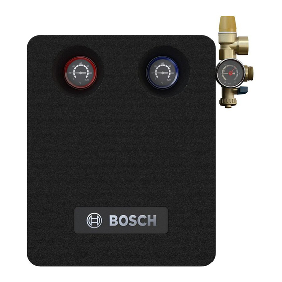
Solar pump station for solar thermal systems
Hide thumbs
1
Table Of Contents
2
3
4
5
6
7
8
9
10
11
12
13
14
15
16
17
18
19
20
21
22
23
24
25
26
27
28
page
of
28
Go
/
28
Contents
Table of Contents
Bookmarks
Table of Contents
1 Key to Symbols and Safety Instructions
Table of Contents
General Safety Instructions
Key to Symbols
2 Information on the Solar Pump Station
Product Description
Determined Use
Components and Technical Documentation
EC Declaration of Conformity
Scope of Delivery
Other Equipment Required
Air Vent Valve
3 Regulations
4 Installing Pipework
General Information Regarding Pipework
Laying Pipes
5 Installing the Solar Pump Station
Layout of the Installation Space
Mounting the Solar Pump Station
Electrical Connection
Installing the Safety Assembly
Connecting the Expansion Vessel and Pre-Cooling
Vessel
Connecting Pipework and Pressure Relief Valve Discharge Pipe to the Solar Pump Station
Installing Temperature Sensors
6 Commissioning
Use of Heat Transfer Fluid
Purging and Filling with a Hand Pump (Air Vent on Roof)
Setting the Flow Rate
Completion of Work
7 Environment / Disposal
8 Commissioning, Inspection and Maintenance Reports
9 Faults
Advertisement
Quick Links
1
Product Description
2
General Information Regarding Pipework
3
Electrical Connection
Download this manual
Solar pump station for solar thermal systems
AGS10-2, AGS10E-2, AGS20-2, AGS50-2
Installation and servicing instructions
Table of
Contents
Previous
Page
Next
Page
1
2
3
4
5
Advertisement
Table of Contents
Need help?
Do you have a question about the AGS10-2 and is the answer not in the manual?
Ask a question
Questions and answers
Related Manuals for Bosch AGS10-2
Water Pump Bosch Worcester AGS 5 Installation And Servicing Instructions
Solar pump stations, for sealed solar heating systems and indirect fed domestic hot water (28 pages)
Water Pump Bosch AGS20-2 Installation And Servicing Instructions
Solar pump station for solar thermal systems (28 pages)
Water Pump Bosch Rexroth A7VO 63 Series Manual
Axial piston variable pump (42 pages)
Water Pump Bosch Rexroth 31 Series Instruction Manual
Axial piston variable pump (60 pages)
Water Pump Bosch Rexroth A10VO Instruction Manual
Axial piston variable pump (60 pages)
Water Pump Bosch Rexroth A10VSNO Instruction Manual
Axial piston variable pumps (60 pages)
Water Pump Bosch REXROTH A4 Series Instruction Manual
Axial piston variable pump with hs5e pilot control valve (104 pages)
Water Pump Bosch Rexroth A10VG Series Repair Manual
Variable pump (36 pages)
Water Pump Bosch Rexroth A4VG 35 Series Instruction Manual
Axial piston variable pump (64 pages)
Water Pump Bosch rexroth A21VG 10 Series Instruction Manual
Axial piston variable double pump a21vg series 10 (56 pages)
Water Pump Bosch rexroth 1 Series Instruction Manual
Axial piston variable double pump (68 pages)
Water Pump Bosch Rexroth A4VG 40 Series Instruction Manual
Axial piston variable pump (68 pages)
Water Pump Bosch rexroth A2FO Series Instruction Manual
Axial piston fixed pump (52 pages)
Water Pump Bosch Rexroth A7VO Instruction Manual
Axial piston variable pump (60 pages)
Water Pump Bosch Rexroth Hyquip 61 Series Operating Instructions Manual
Axial piston variable double pump (52 pages)
Water Pump Bosch Rexroth Hyquip A17FO 10 Series Instruction Manual
Axial piston fixed pump (48 pages)
This manual is also suitable for:
Ags20-2
Ags10e-2
Ags50-2
Table of Contents
Print
Rename the bookmark
Delete bookmark?
Delete from my manuals?
Login
Sign In
OR
Sign in with Facebook
Sign in with Google
Upload manual
Upload from disk
Upload from URL


Need help?
Do you have a question about the AGS10-2 and is the answer not in the manual?
Questions and answers