Table of Contents

Related Manuals for EFI EB-32


Summary of Contents for EFI EB-32
- Page 1 Printer Controller EB-32 Installation and Service Guide A guide for service technicians Replacement parts and specifications are subject to change. For a current parts list, contact your authorized service/support center. 45121967 16 December 2013...
- Page 2 This documentation is protected by copyright, and all rights are reserved. No part of it may be reproduced or transmitted in any form or by any means for any purpose without express prior written consent from Electronics For Imaging (“EFI”), except as expressly permitted herein.
-
Page 3: Table Of Contents
Precautions Creating an electrostatic discharge (ESD) safe environment NSTALLING ARDWARE About the installation process Checking the customer site Setting customer expectations Unpacking the EB-32 Connecting the EB-32 Configuring a static IP address for the EB-32 Completing installation and starting up... - Page 4 ONTENTS EB-32 SING THE EB-32 control panel Activity light Buttons Functions menu Using the copier touch panel Main tab PrintMe tab Job List tab Tools tab Scan tab Fiery tab Printing EB-32 pages Network Status LEDs FieryBar Messages Activity light...
- Page 5 Changing the factory default language Backing up the system configuration Restoring the system configuration Fiery System Restore Installing system software Updating EB-32 system and user software Before updating the EB-32 System updates Check for Product Updates (Software Downloads Site) Remote Desktop...
- Page 6 ONTENTS ROUBLESHOOTING Troubleshooting process Preliminary on-site checkout Checking external connections Checking internal components Inspecting the system Normal startup sequence Error messages and conditions PECIFICATIONS Hardware features Physical specifications Networking and connectivity User software Safety and emissions compliance NDEX...
- Page 7 EB-32 control panel IGURE FieryBar IGURE EB-32 front panel IGURE EB-32 connector panel IGURE Internal side view of the EB-32 IGURE Exploded view of EB-32 components IGURE Data cable connections inside the EB-32 IGURE Power cable connections inside the EB-32 IGURE...
- Page 8 IST OF IGURES Removing the motherboard from the chassis IGURE Removing or replacing a DIMM IGURE CPU cooling assembly IGURE Removing the CPU cooling assembly IGURE Removing/replacing the CPU IGURE Locating the flat corner of the CPU socket IGURE Removing/replacing the chassis fan IGURE Removing/replacing the power supply IGURE...
-
Page 9: Introduction
The EB-32 adds computer connectivity and highly efficient PostScript and PCL printing ability to the Pro 8120S/8110S/8100S. With the EB-32, customers can use the copier as a PostScript printer and scanner. Once it is connected to the copier through the network, customers can print to the EB-32 from supported client computers on the network. -
Page 10: Before You Service The
NTRODUCTION Before you service the EB-32 Before you service the EB-32, it is strongly recommended that you make sure that you have the required tools (page 10) and carefully review all precautions. Also, keep in mind that the most common cause of a hardware problem is a faulty or loose connection. -
Page 11: Precautions
– Do not plug the EB-32 into a switchable power outlet. This can result in the EB-32 being turned off accidentally. • Never set any liquid on or near the EB-32 or the copier. If liquid is spilled into the EB-32 or the copier, disconnect the power cable immediately. -
Page 12: Creating An Electrostatic Discharge (Esd) Safe Environment
• Attach a grounding strap to your wrist. Attach the other end to a good ground. • When you unpack the EB-32 from the carton for the first time, touch a metal area of the copier to discharge the static on your body. - Page 13 NTRODUCTION • Leave new electronic components inside their antistatic bags until you are ready to install them. When you remove components from an antistatic bag, place them on a grounded antistatic surface, component-side up. • When you remove an electronic component, place it in an antistatic bag immediately. Do not walk across a carpet or vinyl floor while carrying an unprotected board.
-
Page 14: Installing Hardware
• “Completing installation and starting up” About the installation process It is strongly recommended that you review this chapter before you install the EB-32. Also keep in mind that installation problems are easier to avoid and diagnose if you proceed from the component level to the system level, verifying functionality at each step. - Page 15 • Network cable (straight-through Ethernet cable) from the upper Ethernet port (see page 6 Complete the installation (see page 22). Remind site administrator to install current user software on client computers that print to the EB-32 (see Printing and Utilities, which are part of the user documentation set).
-
Page 16: Checking The Customer Site
IGURE • Is a dedicated, grounded electrical outlet for the EB-32 available near the copier? Do not run the EB-32 and the copier on the same circuit. If the customer has provided one, use a surge suppressor for the EB-32. -
Page 17: Setting Customer Expectations
NSTALLING ARDWARE Setting customer expectations When the site is ready, installation of the EB-32 takes about 1 hour. Inform the customer of the following: • Some nodes on the network may be unavailable during service. • The network administrator must be available during the installation for network connectivity. -
Page 18: Unpacking The
1 Open the box and remove the packing material. Save the original boxes and packing material in case you need to transport the EB-32 at a later date. 2 Remove the contents from the top accessory tray. Inspect the contents for visible damage. -
Page 19: Connecting The
• Connect to power • Connect to the copier • Connect to the network O CONNECT TO POWER 1 Connect one end of the EB-32 power cable to the power connector on the back of the EB-32 (see Figure 7 on page 39). -
Page 20: Figure 3: Straight-Through And Crossover Ethernet Cables
After power on, the site administrator should perform network setup, verify the network connection, verify that the EB-32 appears in the list of printers, and then print a few test documents from a networked computer that will use the EB-32. For more information, see... -
Page 21: Configuring A Static Ip Address For The
ARDWARE Configuring a static IP address for the EB-32 If the customer requires the EB-32 to be configured with a static IP address (for example, in a non-DHCP network environment), obtain a valid static IP address from the network administrator and configure the EB-32 as described in the following procedure. -
Page 22: Completing Installation And Starting Up
ARDWARE Completing installation and starting up To finish the installation of the EB-32 at the customer site, make sure to do the following: 1 Make sure that the copier is turned on. 2 Set the power switch to the ON position (“|” symbol). -
Page 23: Using The
The control panel LCD continues to draw power when the EB-32 is powered off. • An error has caused printing to be disabled. Flashing or solid red: • The EB-32 is powered off and the AC power cable is not connected to a power No light: source. -
Page 24: Buttons
Avoid using the reset button on the front panel, as doing so may cause the system to operate unpredictably. Use the reset button on the front of the EB-32 only if the system is unresponsive to keyboard or mouse actions. -
Page 25: Using The Copier Touch Panel
SING THE Using the copier touch panel There are tabs on the copier touch panel that are specific to the EB-32. They provide many of the same controls available from Command WorkStation and allow you to view status information, print system pages, and set up printing. For information about the job management features, see Utilities. -
Page 26: Tools Tab
PS Font List: Provides general information about the hardware and software configuration Configuration: of the EB-32, the current Setup options, the current calibration, and the IP address of the EB-32. Prints a procedure for creating a custom paper entry. Custom Paper Instruction: Prints a list of the last 55 jobs. - Page 27 SING THE Clear Server Clears all jobs in all server queues, as well as all jobs archived on the EB-32 hard disk, the index of archived jobs (in the Archive window), all FreeForm masters, and the index of FreeForm masters (in the FreeForm window). Consult with your administrator or operator before choosing Clear Server.
-
Page 28: Printing Eb-32 Pages
EB-32. The following information is also listed: server name, date and time printed, and compression information. When you print a Test Page to confirm that the EB-32-to-copier connection is operating properly, keep in mind that: –... -
Page 29: Network Status Leds
5 Press the name of the page you want to print. Network Status LEDs Two LEDs next to the Ethernet network port indicate the network speed. When data transfer occurs between the EB-32 and the network, the appropriate LED(s) blink to indicate network activity. Network link speed... -
Page 30: Fierybar
FACI is available as an option with this product, but is not a standard feature. FieryBar appears at the top of the monitor when you power on the EB-32. You can use FieryBar to access and control various EB-32 functions. -
Page 31: Commands
• Allows you to run diagnostics on the following option: Run Diagnostics: – Test Email tests the ability of the EB-32 to print a log of all jobs sent using the e-mail printing feature. For more information, see Printing. •... -
Page 32: About Configure
Help. O ACCESS ONFIGURE FROM AN NTERNET BROWSER 1 Open an Internet browser and type the IP address of the EB-32. 2 In WebTools, on the Configure tab, click Launch Configure. 3 Log on with Administrator privileges. O ACCESS ONFIGURE FROM... -
Page 33: Starting, Shutting Down, Restarting, And Rebooting
If you are cycling power, wait at least 10 seconds before powering back on. If you are unable to shut down the EB-32 through the copier touch panel, power off by holding down the power button on the front of the EB-32 for up to eight seconds. - Page 34 EB-32 SING THE EB-32 O START THE 1 Make sure that the copier is turned on. 2 Make sure that the power cable is attached and that the power switch is in the ON position. 3 Press the power button.
- Page 35 RESTART OR REBOOT FROM THE CONTROL PANEL Always verify that the EB-32 is not in use before you begin the following procedure. 1 Make sure that the EB-32 is not receiving, processing, or printing any files. If the system has just finished processing, wait at least five seconds after the system reaches Idle before you proceed.
- Page 36 1 At the copier touch panel, press the Home button. 4 Press the Fiery icon. 1 Make sure that the EB-32 is not receiving, processing, or printing any files. If the system has just finished processing, wait at least five seconds after the system reaches Idle before you proceed.
-
Page 37: Replacing Parts
EPLACING ARTS EPLACING ARTS Generally, the EB-32 requires no regular service or maintenance. Use the procedures in this chapter to inspect, remove, reseat, and replace major hardware components, as well as install system software. Overview This chapter includes information about servicing the following components: •... -
Page 38: Eb-32 Diagrams
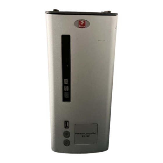
EPLACING ARTS EB-32 diagrams The following figures provide an overview of EB-32 components. 1 Control panel 2 DVD drive 3 USB ports 4 Reset button 5 Power button EB-32 front panel IGURE... -
Page 39: 7: Eb-32 Connector Panel
4 Network port (straight- through Ethernet port) 5 USB ports (x2) 6 Copier interface port (crossover Ethernet port) 7 Video interface port (not used) 8 Power cable 9 Power switch I: Power ON O: Power OFF EB-32 connector panel IGURE... -
Page 40: Figure 8: Internal Side View Of The
2 Copier interface board slot 3 DIMM slots 4 CPU cooling assembly 5 Chassis fan 6 DVD drive 7 Hard disk drive 8 Motherboard Cables, UIB, or OT SHOWN front panel USB port. Internal side view of the EB-32 IGURE... -
Page 41: Figure 9: Exploded View Of Eb-32 Components
20 DVD drive power/data combo cable 5 DIMMs 11 Power supply 16 UIB buttons 21 UIB cable 6 CPU cooling assembly 22 Front panel USB port and cable Tie-wraps, cable clamps, dongle(s), or external cables. OT SHOWN Exploded view of EB-32 components IGURE... -
Page 42: Figure 10: Data Cable Connections Inside The
2 Hard disk drive data cable Hard disk drive Motherboard connector SATA1 3 DVD data combo cable DVD drive Motherboard connector SATA0 4 Front panel USB port cable Front panel USB port Motherboard connector USB A2 Data cable connections inside the EB-32 IGURE... -
Page 43: Figure 11: Power Cable Connections Inside The
Motherboard connector J20, pins 6 (red cable) and 8 (white cable) (see Figure 19 on page 4 CPU fan cable CPU fan Motherboard connector CPUFAN 5 Chassis fan cable Chassis fan Motherboard connector SYSFAN Power cable connections inside the EB-32 IGURE... -
Page 44: Accessing Internal Components
4 Place the EB-32 on a flat surface. Attach an ESD wrist strap before handling internal parts (see “Precautions” on page 11). 5 Carefully position the EB-32 so that it is resting on its side and the internal components are facing up. Place removed components on a grounded, antistatic surface. -
Page 45: Figure 12: Removing/Replacing The Side Panel
EPLACING ARTS O REMOVE AND REPLACE THE SIDE PANEL 1 Shut down the EB-32 (see page 44). 2 Remove the 2 screws that attach the side panel to the back of the chassis. Set aside the screws so that you can replace them later. -
Page 46: Figure 13: Removing/Replacing The Top Panel
ARTS O REMOVE AND REPLACE THE TOP PANEL To remove the top panel, you must first remove the side panel. 1 Shut down the EB-32 (see page 44). 2 From inside the chassis, bend the four tabs that secure the top panel to the chassis until they disengage the slots in the chassis, and then lift the top panel away from the chassis. -
Page 47: Figure 14: Removing/Replacing The Front Panel
ARTS O REMOVE AND REPLACE THE FRONT PANEL To remove the front panel, you must first remove the side and top panels. 1 Shut down the EB-32 (see page 44). 2 From inside the chassis, bend outward on the four tabs that secure the front panel to the chassis, and then lift the panel away from the chassis. -
Page 48: Removing And Replacing Eb-32 Components
EB-32. Also, verify the connections of each replaceable EB-32 component. For more information about troubleshooting, see “Troubleshooting” on page The following sections describe how to remove and install replaceable parts on the EB-32: • Copier interface board • User Interface Board •... -
Page 49: Copier Interface Board
IGURE O REMOVE THE COPIER INTERFACE BOARD 1 Shut down and open the EB-32 (see pages 44). To remove the copier interface board, you must remove the side panel. 2 Remove the two mounting bracket screws that attach the copier interface board to the chassis. -
Page 50: User Interface Board
EPLACING ARTS User Interface Board The User Interface Board (UIB) provides the interface between the EB-32 and the user. The front of the UIB contains circuitry for the following: • Activity lights (amber, green, and red LEDs) • Display window (LCD) •... -
Page 51: Figure 17: Removing/Replacing The User Interface Board
NTERFACE OARD 1 Shut down and open the EB-32 (see pages 44). To access the User Interface Board, you must remove the side, top, and front panels. 2 Detach the UIB cable from the connector on the top of the UIB. -
Page 52: Motherboard
EPLACING ARTS Motherboard This section describes the battery and default jumper settings on the EB-32 motherboard, as well as procedures for removing and replacing the motherboard. Do not move or change any of the default jumper configurations on the motherboard. -
Page 53: Figure 18: Motherboard Battery
1 On a client computer that is connected to the same network as the EB-32, open a Web browser window. 2 In the URL field of the browser, type the IP address or DNS name of the EB-32, and press Enter. -
Page 54: Figure 19: Cable Connections For Power Button
EPLACING ARTS Motherboard jumpers Jumper configuration should not be changed. Jumper Description J4 is the Clear CMOS and Password jumper. Default configuration: jumper cap installed on pins 2 and 3. Because the jumper cap is very small, it is not necessary—and could introduce an error—to remove the jumper cap in order to clear the Pin 1 CMOS settings. -
Page 55: Figure 20: Diagram Of The Eb-32 Motherboard
13 CPU fan connector (CPUFAN J17) 6 DIMM (DIMM A1) 14 Chassis fan connector (SYSFAN J23) 7 DIMM (DIMM A0) 15 DVI+VGA port 8 Scan crossover connector (10/100BaseT), USB connectors (x2) 16 For front panel USB port (USB A2) Diagram of the EB-32 motherboard IGURE... - Page 56 Follow standard ESD precautions while handling the motherboard and all components. For details, see “Precautions” on page O REMOVE MOTHERBOARD COMPONENTS FROM THE MOTHERBOARD 1 Access and open the EB-32, as described on page 2 Remove the following cables attached to the motherboard: • Reset button cable •...
-
Page 57: Figure 21: Removing The Motherboard From The Chassis
EPLACING ARTS O REMOVE THE MOTHERBOARD Follow ESD and other safety precautions when handling the motherboard. Do not touch the contacts and avoid using excessive force. Place the motherboard on a grounded, antistatic surface. 1 Remove the power supply (see page 70). - Page 58 – First, replace the HDD and install system software. Always replace a faulty HDD with a new HDD. Transferring a HDD from one EB-32 to another is incorrect and strongly discouraged. – If the problem persists, reinstall the original HDD in the system, and then replace the...
- Page 59 EPLACING ARTS Motherboard cautions If you have exhausted all other troubleshooting remedies and determined that you need to install a new motherboard, be sure to observe the following cautions: • Follow ESD and other safety precautions when handling the motherboard. If you need to remove the motherboard during service, place it on a grounded, anti-static surface.
- Page 60 • UIB cable • DVD data cable • Hard disk drive data cable • Motherboard power cable • CPU power cable • Chassis fan power cable 2 Reinstall the copier interface board (see page 49). 3 Reassemble the EB-32 (see page 79).
-
Page 61: Verifying New Motherboard Installation And Transferring Options
EPLACING ARTS Verifying new motherboard installation and transferring options After you install a new motherboard and reassemble the system, do the following: • Verify all functionality by using the motherboard replacement dongle to enter Service Mode. (Service Mode is not indicated on the monitor or LCD, but is entered once you power on with a new motherboard installed and the motherboard replacement dongle installed on a USB port.) Service Mode is a temporary state that allows you to make sure that the motherboard... - Page 62 4 Power on the EB-32 and allow it to boot without interruption. At this point the EB-32 is in Service Mode, so you can verify that the new motherboard solves the problem that you are trying to troubleshoot. Service Mode is not indicated on the monitor or on the EB-32 control panel.
-
Page 63: Replacing Parts On The Motherboard
BIOS from the hard disk drive to the BIOS chip on the replacement motherboard. If you select “No” the process ends and you return to the Functions menu. 6 Reboot the EB-32. 7 Remove the motherboard replacement dongle after the EB-32 reaches Idle on the copier touch panel. 8 Reinstall system software. -
Page 64: Dimm(S)
DIMM O REMOVE OR REPLACE A 1 Shut down and open the EB-32 (see pages 44). To remove a DIMM, you must remove the side panel. 2 To release a DIMM, push outward on the levers on each side of the DIMM. -
Page 65: Cpu And Cpu Cooling Assembly
EPLACING ARTS CPU and CPU cooling assembly The CPU is installed in a socket on the motherboard. Before removing the CPU from its socket, remove the motherboard from the chassis (see page 56), disconnect the CPU fan cable from the motherboard, and remove the cooling assembly from the CPU socket (see page 66). -
Page 66: Figure 24: Removing The Cpu Cooling Assembly
EPLACING ARTS O REMOVE A 1 Access and open the EB-32, as described on page 2 Remove the motherboard components (see page 56). 3 Remove the power supply (see page 70). 4 Remove the motherboard from the chassis (see page 57). -
Page 67: Figure 25: Removing/Replacing The Cpu
EPLACING ARTS 9 Open the load plate (see Figure 25). Yellow triangle Socket lever in the open position Flat corner of socket border Socket lever in the locked position Load plate open Removing/replacing the CPU IGURE 10 Grasp the CPU by its edges, lift it out of the socket, and then place the CPU in a safe place. If you remove the CPU from the motherboard to install it on a new motherboard, unpack the new motherboard and remove the protective plastic cover from the CPU socket. -
Page 68: Figure 26: Locating The Flat Corner Of The Cpu Socket
EPLACING ARTS 3 Place the CPU in the socket (see Figure 25 on page 67). The CPU and the socket are keyed to ensure correct installation. The notches on the edges of the CPU correspond with the two small posts inside the socket. Align the yellow triangle on the CPU with the yellow arrow stenciled on the motherboard next to the socket. -
Page 69: Chassis Fan
A fan mounted inside the chassis blows air out of the EB-32 to cool components. The chassis fan runs continuously when the system is on. You should hear the chassis fan start as soon as you power on the EB-32. If you do not hear the chassis fan, there may be a faulty power connection (see Figure 11 on page 43). -
Page 70: Power Supply
5 Verify EB-32 functionality (see page 79). Power supply This section describes how to remove and replace the EB-32 power supply. For more information on the power supply, see “Specifications” on page 115. You can check power supply functionality using a multimeter at the power cable connectors supplying power to the motherboard, CPU, HDD, and DVD drive. -
Page 71: Figure 28: Removing/Replacing The Power Supply
EPLACING ARTS 9 Lift the power supply out of the chassis, taking care to gather the power supply cables. Power supply cables Power supply Screw (1 of 5) Removing/replacing the power supply IGURE... - Page 72 • DVD drive and hard disk drive SATA cables (see Figure 10 on page • Power and reset button cables (see Figure 11 on page • Copier interface board (see page 10 Reassemble the EB-32 and verify its functionality (see page 79).
-
Page 73: Hard Disk Drive
Proper handling Improper handling can damage a hard disk drive. Handle hard disk drives with extreme care. • Use proper ESD practices when grounding yourself and the EB-32. • Keep magnets and magnetic-sensitive objects away from the hard disk drive. -
Page 74: Figure 29: Removing/Replacing The Hard Disk Drive Bracket
If desired, back up the system configuration (see page 82). 2 Shut down and open the EB-32 (see pages 44). To access the hard disk drive, you must remove the side and front panels. 3 Remove the DVD drive (see page 77). -
Page 75: Figure 30: Removing/Replacing The Hard Disk Drive From The Hard Disk Drive Bracket
EPLACING ARTS 8 Remove the four screws that attach the hard disk drive to the hard disk drive bracket (see Figure 30 on page 75). Hard disk drive bracket Screw (1 of 4) Hard disk drive Removing/replacing the hard disk drive from the hard disk drive bracket IGURE 9 Remove the hard disk drive from the hard disk drive bracket and place it in an antistatic bag. - Page 76 Do not install a new hard disk drive and a new motherboard at the same time. If you suspect that the EB-32 needs a new hard disk drive and a new motherboard, first install the new hard disk drive and install system software (see...
-
Page 77: Dvd Drive
O REMOVE THE DRIVE 1 Shut down and open the EB-32 (see pages 44). To remove the DVD drive, you must remove the side and front panels. 2 Remove the DVD drive power/data combination cable from the back of the DVD drive. -
Page 78: Figure 32: Removing/Replacing The Dvd Drive
Figure 10 on page 42 Figure 11 on page 43). 4 Reassemble the EB-32 and verify functionality (see page 79). 5 If you installed a new DVD drive, make sure to reset the system date and time. For more information, see... -
Page 79: Restoring And Verifying Functionality After Service
19). 7 Print the Test Page and Configuration page. • If the EB-32 does not start up, see startup problems on page 105. • If pages do not print, verify that the interface cables are properly connected (see printing... -
Page 80: Nstalling System Oftware
The following issues apply to the scenario where you reinstall the system from the System Software DVDs. • All jobs in all print queues, and all jobs archived locally on the EB-32 hard disk drive Jobs: are deleted when you reinstall the system software. To save jobs, ask the site administrator to archive them to a CD/DVD or a location on the network, so that the jobs can be imported back into the EB-32 queue after system software installation. - Page 81 For optimal performance, maintain current versions of the user User software updates: software on every network computer used to print to the EB-32. User software may be installed directly on client computers equipped with a DVD drive, or over a network via the Fiery User Software Installer that resides on the EB-32.
-
Page 82: Changing The Factory Default Language
NSTALLING YSTEM OFTWARE Changing the factory default language Before installing system software, you can change the EB-32 default language preinstalled at the factory using the Configure tool, available through Command WorkStation and WebTools. O CHANGE THE FACTORY DEFAULT LANGUAGE 1 Open Configure through either Command WorkStation or WebTools. -
Page 83: Restoring The System Configuration
4 Enter a file name, select a location, and click Next. 5 Click Finish. Restoring the system configuration You can restore the configuration of the EB-32 to its previous state using a configuration file. For more information about a configuration file, see “To save the system configuration”... -
Page 84: Fiery System Restore
OFTWARE Fiery System Restore The EB-32 system installer allows you to back up or restore the entire system to recover from a system crash or a hard disk failure. You can start the system installer from System Software DVD 1 to create a new system backup partition of the EB-32, load a system recovery partition to restore the EB-32 to an earlier state, or use utilities to troubleshoot and administer the EB-32. - Page 85 • The recovery partition, which restores the default system settings from a hidden hard disk drive partition. • Search for a backup that you have created on the EB-32. The installer begins the recovery process. If you must search for backups, use the following steps.
-
Page 86: Installing System Software
Install system software in the following cases: • The hard disk drive is replaced. • The EB-32 must be updated to a more recent version of the system software. • The language settings need to be changed. O INSTALL SYSTEM SOFTWARE Notify the network administrator at the customer site that some archived jobs may no longer print after you install an updated version of system software. - Page 87 This segment takes approximately 45 minutes. During this process, the following installations are performed: • The entire contents of the User Software DVD are copied to a shared folder on the EB-32 hard disk drive, in e:\efi\user_sw.
- Page 88 (Assumes a monitor, keyboard, and mouse are connected to Using Command WorkStation: the EB-32.) From the Server menu, choose Configure, and then configure Setup using the Configuration page that you printed earlier. Bypass any settings if it is more appropriate for the network administrator to set them.
-
Page 89: Updating Eb-32 System And User Software
Using the tools System Updates and Check for Product Updates (Software Downloads Site), you can obtain updates to EB-32 System Software and User Software from a secure site on the Internet (referred to throughout this documentation as the Update Server). -
Page 90: System Updates
EB-32. The updated applications are first downloaded from the Update Server to a partition on the EB-32 HDD. Users access the EB-32 over the Internet and download the updated applications onto client computers and then manually install them. - Page 91 5 Do one of the following: • From Configure, click Apply. • From the FACI, click OK. • If you logged on to the EB-32 with Remote Desktop, click OK. O USE HECK 1 From the Fiery Advanced Controller Interface (FACI), click Start > All Programs > Fiery >...
-
Page 92: Check For Product Updates (Software Downloads Site)
• Updates that are unavailable through System Updates and/or are not approved for all users. • Updates that may already be installed on some EB-32 print servers. To help you choose the updates to download, compare the list displayed with the EB-32 print server’s Configuration Page >... -
Page 93: Figure 33: Software Download Site Example (Page Varies By Product)
• Updates that are unavailable through System Updates and/or are not approved for all users. • Updates that may already be installed on some EB-32 print servers. To help you choose which updates to download, compare the list displayed with the EB-32 print server’s Configuration Page >... -
Page 94: Remote Desktop
YSTEM OFTWARE Remote Desktop Since the EB-32 is Windows-based, you can use Remote Desktop to access the EB-32 from a remote computer. Remote Desktop Connection is a Microsoft application that allows you to access one Windows computer from another. To use EB-32 with Remote Desktop, you must enable Remote Desktop in Setup and on the client computer. -
Page 95: Troubleshooting
ROUBLESHOOTING ROUBLESHOOTING This chapter identifies the source of common problems that may occur with the EB-32 and suggests ways of correcting the problems. Troubleshooting process Problems with the EB-32 configuration may occur in one of three areas: • Inside the EB-32 •... -
Page 96: Checking External Connections
Checking external connections Before removing the side and front panels of the EB-32 to check internal components, eliminate the most obvious sources of problems. Make sure that: • All interface cables to the system are plugged into the proper connectors... -
Page 97: Checking Internal Components
ROUBLESHOOTING Checking internal components To check the internal components, you must remove the side and front panels of the EB-32. Before you remove the EB-32 panels, be aware of the safety precautions that you should take when handling the EB-32. Use ESD precautions when handling printed circuit boards and electronic components. -
Page 98: Inspecting The System
(for example, if the system hangs before reaching Idle), locate the symptom in “Table 3: EB-32 error messages and conditions” on page 105 and perform the suggested action(s) for the condition. - Page 99 • Each DIMM is well-seated. • Battery is installed. • BIOS is well seated. • Each DIMM is well-seated. DIMM(s) for EB-32, page 64 • DIMM edge connectors are not oxidized. Copier interface board is: Copier interface board, page 49 •...
- Page 100 ROUBLESHOOTING Verifying the system ABLE Conditions to verify Part and additional page references The power supply required is: Power supply, page 70 • Present • Correctly installed • Appears undamaged Cable connectors are: • Firmly connected • Appear undamaged • Installed in the correct devices The hard disk drive required is: Hard disk drive, page 73...
- Page 101 ROUBLESHOOTING Verifying the system ABLE Conditions to verify Part and additional page references Each cable required is: UIB cable, Figure 10 on page 42 • Present • The correct type • Installed in the correct connector • Well-seated Hard disk drive data cable, Figure 10 on page 42 •...
- Page 102 For the following items, see the document are present and appear undamaged. The mouse and keyboard are that accompanies the optional components, if connected to the correct ports on the EB-32 connector panel. applicable. • Mouse (if applicable) The cables required are: •...
-
Page 103: Normal Startup Sequence
ROUBLESHOOTING Normal startup sequence When you turn on or reboot the EB-32, the system runs the following startup routine on the EB-32 control panel. The sequence takes approximately two minutes to complete. The following table lists the normal startup sequence as it appears on the EB-32 Control Panel and on the monitor. -
Page 104: Error Messages And Conditions
Always replace a faulty hard disk drive with a new hard disk drive. Transferring a hard disk drive from one EB-32 to another is incorrect and strongly discouraged. • If the problem persists, reinstall the original hard disk drive in the system, and then replace the motherboard. - Page 105 • Power cable is not plugged into ON position (see page 34). the power connector on the EB-32 Activity light status: Off. connector panel or into the wall power 3 Listen for the power supply fan and feel for air at the back outlet.
- Page 106 ROUBLESHOOTING Symptom Possible cause Suggested action Startup (cont.) EB-32 is getting power, • UIB cable is not connected to the 1 Recheck all cables and connections. but the control panel motherboard, the User Interface Board, 2 Use a different UIB cable.
- Page 107 Control panel screen Possibly one of the following: 1 Recheck all cables and connections. and Activity light appear 2 Reboot the EB-32. • Wrong, missing, incorrectly connected, as follows: or faulty DIMM(s) 3 If the problem persists, verify that the DIMM(s) are...
- Page 108 • Problem with system software to solid red. 2 Recheck all cables and connections. • Print job is corrupt or too large 3 Reboot the EB-32 and check whether the CPU cooling Activity light status: Solid green, then • Faulty UIB cable assembly fan is operating.
- Page 109 • The copier is on but is not ready • Recycle power on the copier. to print. • Recycle power on the EB-32 by shutting down the system, waiting 10 seconds, and then powering the EB-32 back on (see page 33).
- Page 110 The EB-32 hangs during Possibly one of the following: 1 Set the time and date in the BIOS: system software • Power off the EB-32 and remove any media from the DVD • The system time and date need to be installation. drive.
- Page 111 If you suspect a network problem, keep in mind the following: • If the EB-32 does not appear in the list of printers on the network, there may be another device on the network with the same Ethernet hardware address.
- Page 112 Possibly one of the following: 1 Make sure that the correct cables are connected to the then displays one or more correct ports on the EB-32 connector panel. The upper • Network cable is connected to DHCP error messages Ethernet port is for the network straight-through cable; the the wrong Ethernet port.
- Page 113 EB-32 appears in the list of A PostScript error Make sure that Print to PostScript Error in Setup is set to Yes. Check for error messages on the EB-32 output. printers on the customer’s workstation, but certain jobs do not print.
- Page 114 (For more information, see Printing.) If the user can print the EB-32 Test Page but cannot print a job from a computer on the network, make sure that the network administrator has: • Checked all components of the network, including cables, connectors, terminators, network adapter boards, and network drivers.
-
Page 115: Specifications
PECIFICATIONS PECIFICATIONS This section provides an overview of EB-32 features, specifications, and safety certifications. Replacement parts and specifications are subject to change. When ordering replacement parts, refer to the current parts list maintained by your authorized service/support center. Install the correct parts as directed by your service/support center. -
Page 116: Networking And Connectivity
For optimal performance, maintain current versions of the user software on every network computer used to print to the EB-32. User software may be installed directly on client computers, or over a network via the Fiery User Software Installer that resides on the EB-32. Safety and emissions compliance The EB-32 has been certified to meet or surpass the following government standards. -
Page 117: Index
NDEX NDEX Numerics Cancel Print command, from FieryBar 31 Cancel Processing command, from FieryBar 31 10BaseT/100BaseTX/1000BaseT 20 CD, ejecting 24 changing the server’s default language 14 AC connector 96 chassis fan 43 activity light 23 check for product updates 92 status during startup 107 Check Now feature, system updates 90 AppleTalk 116... - Page 118 NDEX connectors down button 23 back panel 96 drives chassis fan 55 DVD 77 CPU fan cable 55 hard disk drive (HDD) 73 DIMMs 55 DVD drive 77 DVD drive data cable 55 bracket 78 front panel USB port 55 power/data combination cable 42 HDD data cable 55 removing 77...
- Page 119 NDEX motherboard battery 55 hard disk drive (HDD) 73 battery on 52 bracket 73 connectors 55 capacity 115 – installation of 59 caution about replacing 76 jumper pins 54 data cable 74 – removal of 56 description 73 transferring options to 61 mounting screws 75 –...
- Page 120 NDEX printing system software, updating 91 Configuration page 26 system updates Font List 28 cautions 89 font list 26 Check Now feature 90 Job Log 28 enabling a proxy server 91 server information pages 26 enabling Remote Desktop 94 profiles 81 scheduling 91 proxy server 91 Test Email command, from FieryBar 31...
Need help?
Do you have a question about the EB-32 and is the answer not in the manual?
Questions and answers