Advertisement
Quick Links
801 Avenida Acaso, Camarillo, Ca. 93012 • (805) 494-0622 •
www.sdcsecurity.com • E-mail: service@sdcsecurity.com
I. Features & Benefits
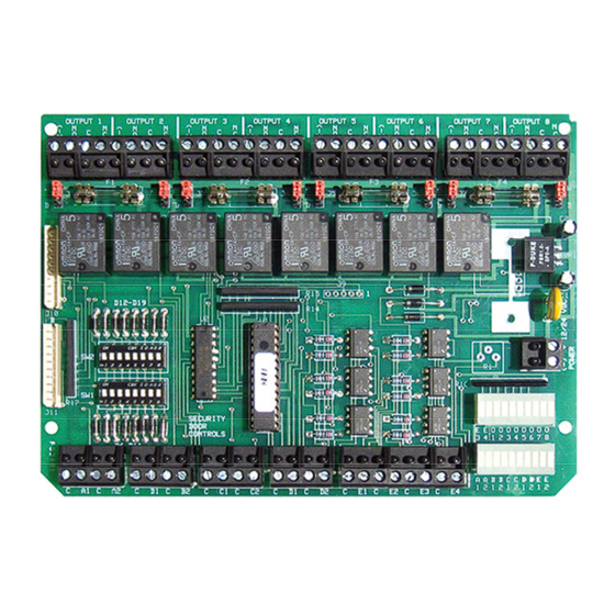
Microprocessor based relay controller that provides 7
different, field selectable application modes for two, three or
four door stations
3 field selectable Interlock (airlock) modes
Field selectable Communicating (shared) bathroom mode
Field selectable relay modes include:
- Conventional Relay (CR)
- Latching Relay (LR) – Pulse on, pulse off
- Time Delay Relay (TD) – 1-65 seconds
- Dual Function Relay (CR/LR, TD/LR, TD/CR, CR/CR)
Each output relay is field selectable as a dry contact or a
voltage output
II. Technical Specifications
Input Voltage:
Input Current:
Relay Inputs:
Auxiliary Inputs:
Relay Outputs:
Dimensions:
P:\INSTALLATION INST\Power Supplies\INST-UR\INST-UR4-8.vsd
INSTALLATION INSTRUCTIONS
MODEL UR4-8
UNIVERSAL DOOR CONTROLLER
12 or 24VDC +/- 10%
250/130 mA max. @ 12/24 VDC
8-SPST, Dry, Optically Isolated
All Normally Open or Normally Closed (field selectable)
4-SPST, Dry, Normally Open, Optically Isolated
4 fused SPDT relays, 7A @ 30VDC
4 non-fused SPDT relays, 7A @ 30VDC
Individually configurable as a dry contact or voltage output (field selectable)
7" W x 5" H x 2" D
(177.8 x 127 x 50.8 mm)
REV A1
11-14
Centralized wiring for all locks, access controls, monitoring
contacts, and peripheral equipment
Onboard input/output status lights for easy troubleshooting
3 system control inputs: Lock All, Unlock All, System
Lockout
Emergency release input for fire panel interface
Removable terminal blocks simplify installation
1 or 2 controllers may be installed in SDC 600 series power
supplies
Page 1
Advertisement

Related Manuals for SDC UR4-8


Summary of Contents for SDC UR4-8
- Page 1 Removable terminal blocks simplify installation - Latching Relay (LR) – Pulse on, pulse off - Time Delay Relay (TD) – 1-65 seconds 1 or 2 controllers may be installed in SDC 600 series power - Dual Function Relay (CR/LR, TD/LR, TD/CR, CR/CR) supplies...
- Page 2 INPUT POWER CONNECTION – The UR4-8 must be powered by a filtered and regulated 12 or 24VDC Power Supply. SDC 600 The relay output voltage will be the same as the UR4-8 input Series Power Supplies are designed to accommodate and voltage (12 or 24 VDC).
- Page 3 Section VIII – Dual Relay Control Mode – Go To Pages 11 & 12 In Dual Relay Control Mode, the UR4-8 operates as four (4) individually controlled relay stations. Each station provides: (1) Fused, SPDT lock output, wet or dry,...
-
Page 4: Emergency Override
IV. Applications (Continued) Section IX – Single Relay Control Mode – Go To Pages 13 & 14 In Single Relay Control Mode, the UR4-8 operates as eight (8) individually controlled relay stations. FAIL- FAIL- SAFE SAFE Stations A1, B1, C1, & D1 each provide:... - Page 5 Refer to the INTERLOCK “A” MODE wiring diagram on Page 6. The UR board Relay Outputs must be protected against WARNING!: NOTE: It is assumed that the UR4-8 and locking hardware share the inductive kickback generated when power is removed from an inductive same power supply.
- Page 6 P:\INSTALLATION INST\Power Supplies\INST-UR\INST-UR4-8.vsd REV A1 11-14 Page 6...
- Page 7 Refer to the MANTRAP “B” MODE wiring diagram on Page 8. The UR board Relay Outputs must be protected against WARNING!: NOTE: It is assumed that the UR4-8 and locking hardware share the inductive kickback generated when power is removed from an inductive same power supply.
- Page 9 Refer to the INTERLOCK “C” MODE wiring diagram on Page 10. The UR board Relay Outputs must be protected against WARNING!: NOTE: It is assumed that the UR4-8 and locking hardware share the inductive kickback generated when power is removed from an inductive same power supply.
- Page 11 The UR board Relay Outputs must be protected against WARNING!: inductive kickback generated when power is removed from an inductive NOTE: It is assumed that the UR4-8 and locks will share the same power load (e.g., electric strikes). Refer to the lock manufacturer's installation supply.
- Page 12 P:\INSTALLATION INST\Power Supplies\INST-UR\INST-UR4-8.vsd REV A1 11-14 Page 12...
- Page 13 Follow the Single Relay Control Mode wiring diagram for fail-safe or fail- secure locks. Be careful to observe lock voltage polarity. NOTE: It is assumed that the UR4-8 and locks will share the same power supply. The UR board Relay Outputs must be protected against...
- Page 15 Page 16. recommendations. It is assumed that the UR4-8 and locks will share the same power supply. NOTE: All lock monitoring options below (LBM, DPS, and/or REX) shown wired so that the circuit is OPEN when the doors are CLOSED and LATCHED.
- Page 16 P:\INSTALLATION INST\Power Supplies\INST-UR\INST-UR4-8.vsd REV A1 11-14 Page 16...
Need help?
Do you have a question about the UR4-8 and is the answer not in the manual?
Questions and answers