Table of Contents
Advertisement
Available languages
Available languages
Quick Links
OBO Bettermann GmbH & Co. KG
Postfach 1120
58694 Menden
Germany
www.obo-bettermann.com
MCF 35-1+FS-440
MCF-MS-P3
DE
Ableiter Typ 1 für
Energieversorgungsanlagen
Montage- und Installationsanleitung
EN
Lightning current arrestor type 1
for power supply systems
Mounting and installation instructions
1
5
4
3
2
1
ok
2
ok
ok
12
14
11
Advertisement
Table of Contents

Related Manuals for OBO Bettermann MCF 35 Series


Summary of Contents for OBO Bettermann MCF 35 Series
- Page 1 MCF 35-1+FS-440 MCF-MS-P3 Ableiter Typ 1 für Energieversorgungsanlagen Montage- und Installationsanleitung Lightning current arrestor type 1 for power supply systems Mounting and installation instructions OBO Bettermann GmbH & Co. KG Postfach 1120 58694 Menden Germany www.obo-bettermann.com...
- Page 2 10 Nm MCF-MS-M10 10 Nm MCF-MS-P1 ∅ M10 5 Nm 10 Nm 5 Nm...
- Page 3 M8 x 25 10 Nm MCF-MS-P3 10 Nm 257 mm MCF-MS-P3 MCF-MS-P3 M8 x 16 10 Nm...
- Page 7 MCF 35-1+FS-440, Art . 5096 974 MCF-MS-P3, Art . 5096 992 DE Montage- und Installations a nleitung . . . . 7 EN Mounting and installation instructions . . 11 EG-Konformitätserklärung / EC Declaration of conformity . . . . . . . . 15...
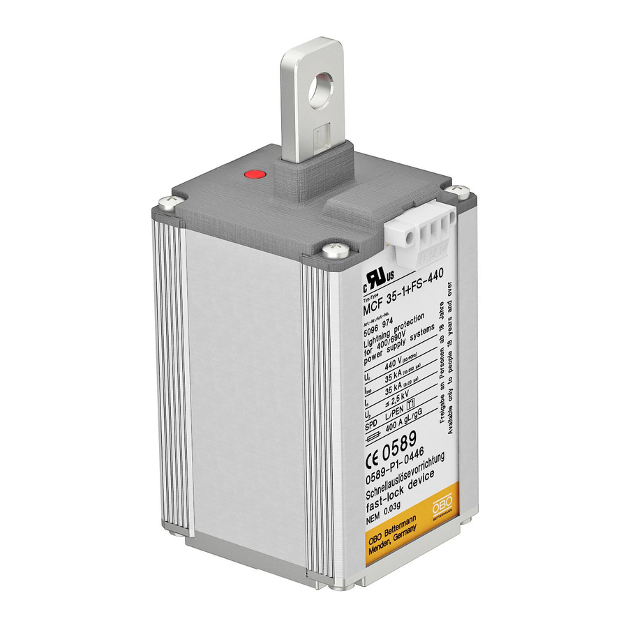
- Page 9 DE Montage- und Installations- anleitung Produktbeschreibung MCF 35-1+FS-440 Bild Einpoliger Blitzstromableiter Typ 1 zum Blitzschutz- potentialausgleich von Energieversorgungsanlagen nach DIN EN 62305 (IEC 62305) . Gekapselte, nicht ausblasende Funkenstreckentechnologie, geeignet für den Innenbereich (z . B . Verteilergehäuse) . Integrierte Abtrennvorrichtung unterbricht im Fehlerfall die Netz- verbindung, dadurch optische Anzeige sowie Fern- signalisierung mit potentialfreiem Wechslerkontakt (siehe auch Bild ) . Anschluss an Leiter L mittels Ka- belschuh (siehe auch Bild Lieferumfang, siehe Bild Blitzstromableiter MCF 35-1+FS-440 Stecker für Fernsignalisierung Phasenanschluss-Set Schrumpfschlauch Produktbeschreibung MCF-MS-P3 Bild 3 x MCF 35-1+FS-440, vormontiert auf Montageplatte . Inkl . 2 Schrauben M8 x 16 für Wandmontage, 3 Schrau- ben M8 x 25 für Befestigung auf Sammelschiene, so- wie Muttern und Unterlegscheiben für Erdanschluss...
-
Page 10: Allgemeine Sicherheitshinweise
Zielgruppe Montage und Anschluss des Gerätes dürfen nur durch eine Elektrofachkraft erfolgen . Allgemeine Sicherheitshinweise – Vor dem Arbeiten mit Stromleitungen die Span- nungsfreiheit herstellen und gegen Wiederein- schalten sichern! – Montage nicht bei Gewitter durchführen! – Nationale Gesetze und Normen beachten (z . B . IEC 60364-5-53; VDE 0100 Teil 534)! Montage und Installation – Einzelgerät auf Montageplatte (Zubehör) b efestigen: Bild : MCF-MS-P1 für Sammelschienenmontage (Art .-Nr . 5096 994), Bild : MCF-MS-M10 für direkte Sammelschienen- montage (Art .-Nr . 5096 990) . –... -
Page 11: Technische Daten
– Installation gemäß den Schaltbildern IT-System IT-System mit Neutralleiter TN-C-System Defektanzeige Bei Defektanzeige (Bild ) Gerät austauschen . Entsorgung Verpackung wie Hausmüll, Artikel wie Sondermüll (Ab- fallschlüsselnr . 59101) entsorgen . Beachten Sie die ört- lichen Müllentsorgungsvorschriften . Technische Daten MCF 35-1+FS-440 SPD-Typ nach EN 61643-11 Type I Blitzschutzzone 1 → 2 Höchste Dauerspannung U 440 V AC / 50-60 Hz Kurzschlussfestigkeit I 50 kA SCCR Schutzleiterstrom I < 1 mA a .c . Folgestromlöschvermögen I 50 kA Dauerbetriebsstrom I – Schutzpegel U ≤ 2 .5 kV TOV-Festigkeit 760 V/5 s Nennableitstoßstrom In 35 kA (8/20) Blitzstoßstrom I... - Page 12 Ports One-Port-SPD Schutzpfad L/PEN Prüfnorm IEC 61643-11 Ed . 1 .0 DIN EN 61643-11 Schutzart IP 20 Temperaturbereich -40 °C … +85 °C Luftfeuchte 5 % … 95 % Anschlussquerschnitt, starr 16 - 50 mm² Anschlussquerschnitt, 16 - 50 mm² mehrdrähtig Anschlussquerschnitt, flexibel 16 - 50 mm² Abmessungen L x B x H 73 x 70 x 159 mm Gewicht 980 g MCF-MS-P3 Bestückung 3 x MCF 35-1+FS-440 Abmessungen L x B x H 288 x 123 x 166 mm Gewicht 5000 g Fernsignalisierung Anschlussquerschnitt 0,14 - 2,5 mm² Abisolierlänge 6 mm Max . Betriebsspannung 250 V AC Max . Betriebsstrom 1,5 A AC...
- Page 13 EN Mounting and installation instructions Product description MCF 35-1+FS-440 Figure Single pole lightning current arrestor type 1 for lightning current equipotential bonding of power sup- ply systems acc . to IEC 62305 . Encapsulated, non extinguishing spark gap arrestor for inside use (e .g . distributor housings) . In case of an error, the integrat- ed disconnector unit interrupts the power supply, shown by a visual indicator as well as remote sig- nalling with potential-free changeover contact...
-
Page 14: Target Group
Target group Mounting and installation of the device may only be carried out by an electical technician . General safety information – Before working on power cables, ensure that they are deenergised, and secure them against uninten- tional switch-on! – Do not carry out mounting work during a storm! – Comply with national laws and regulations (e . g . IEC 60364-5-53; VDE 0100 part 534)! Mounting and installation – Mounting of single device on mounting plate (accessory): Fig . : MCF-MS-P1 for bus bar mounting (item no . 5096 994), Fig . -
Page 15: Error Indication
– Installation as shown on wiring diagrams IT system IT system with neutral conductor TN-C system Error indication If an error occurs as shown on fig . , the device has to be replaced . Disposal Dispose packaging as household waste, device as haz- ardous waste (waste code no . 59101) . Comply with the local waste disposal regulations . Technical data MCF 35-1+FS-440 SPD type acc . to EN 61643-11 Type I 1 → 2 Max . continuous operating 440 V AC / 50-60 Hz voltage U Short circuit current rating I 50 kA SCCR Residual current I < 1 mA a .c . Follow current interrupt rating I 50 kA Continuous operating current I – Voltage protection level U ≤ 2 .5 kV TOV protection 760 V/5 s... - Page 16 Max . backup fuse 400 A gL/gG Ports One-Port-SPD Protection mode L/PEN Test standards IEC 61643-11 Ed . 1 .0 DIN EN 61643-11 Protection rating IP 20 Temperature range -40 °C … +85 °C Humidity 5 % … 95 % Connection cross-section, rigid 16 - 50 mm² AWG 6 – AWG 1 Connection cross-section, 16 - 50 mm² multi-wire AWG 6 – AWG 1 Connection cross-section, 16 - 50 mm² fl exible AWG 6 – AWG 1 Dimensions L x B x H 73 x 70 x 159 mm Weight 980 g MCF-MS-P3 Equipment 3 x MCF 35-1+FS-440 Dimensions L x B x H 288 x 123 x 166 mm Weight 5000 g Remote signalling Connection cross-section...
- Page 17 EG-KONFORMITÄTSERKLÄRUNG EC DECLARATION OF CONFORMITY...
- Page 18 EG-KONFORMITÄTSERKLÄRUNG EC DECLARATION OF CONFORMITY...
Need help?
Do you have a question about the MCF 35 Series and is the answer not in the manual?
Questions and answers