Table of Contents
Advertisement
Quick Links
INSTALLATION MANUAL
AIR
CONDITIONER
* Please read this installation manual completely before installing
the product.
* Installation work must be performed in accordance with national wiring
standards by authorized personel only.
* Please retain this installation manual for future reference after read it
throughly.
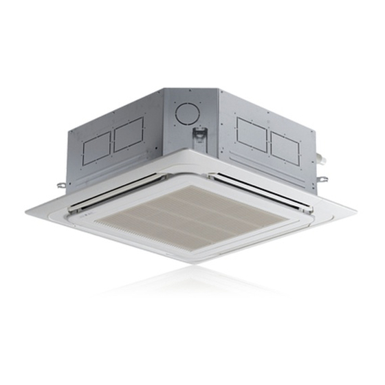
TYPE : CEILING CASSETTE AIR CONDITIONER
*MFL63260113*
Rev. : 01(05T15)
www.lg.com
Advertisement
Table of Contents

Related Manuals for LG AT-C186PLE1


Summary of Contents for LG AT-C186PLE1
- Page 1 * Installation work must be performed in accordance with national wiring standards by authorized personel only. * Please retain this installation manual for future reference after read it throughly. TYPE : CEILING CASSETTE AIR CONDITIONER *MFL63260113* Rev. : 01(05T15) www.lg.com...
-
Page 2: Table Of Contents
Cassette Type Air Conditioner Installation Manual TABLE OF CONTENTS Installation Required Parts Required Tools Requirements Important Safety Instructions ..3 • Connecting cable • Horizontal meter • Pipes: Gas side • Screw driver Liquid side Introduction ........5 • Electric drill •... -
Page 3: Important Safety Instructions
Important Safety Instructions Important Safety Instructions Always comply with the following precautions to avoid dangerous situations and ensure peak performance of your product WARNING It can result in serious injury or death when the directions are ignored CAUTION It can result in minor injury or product damage when the directions are ignored WARNING •... - Page 4 Important Safety Instructions • Do not let the air conditioner run for a long time when the humidity is very high and a door or a window is left open. - Moisture may condense and wet or damage furniture. • Use a vacuum pump or Inert (nitrogen) gas when doing leakage test or air purge. Do not compress air or Oxygen and Do not use Flammable gases.
-
Page 5: Introduction
Introduction Introduction Symbols used in this Manual This symbol alerts you to the risk of electric shock. This symbol alerts you to hazards that may cause harm to the air conditioner. This symbol indicates special notes. NOTICE Features Anti-bacteria filter Intake Air Outlet Wireless Remote Controller... -
Page 6: Installation
Installation Installation Installation Tools Figure Name Figure Name Screw driver Ohmmeter Electric drill Hexagonal wrench Measuring tape, Knife Ampmeter Hole core drill Gas-leak detector Thermometer, Spanner Horizontal meter Torque wrench Flaring tool set Manifold gage Vacuum pump Ceiling Cassette Air Conditioner... -
Page 7: Selection Of The Best Location
Installation Selection of the best location 1) Indoor unit • There should not be any heat source or steam near the unit. • There should not be any obstacles to prevent 10 or more the air circulation. Ceiling Ceiling Board •... - Page 8 3) Select a well-drained place. 1. If you can’t meet above guide line in the seaside installation, please contact LG Electronics for the additional anticorrosion treatment. 2. Periodic ( more than once/year ) cleaning of the dust or salt particles stuck on the heat exchanger by using water...
- Page 9 Pipe Size Length Elevation *Additional (Diameter:Ø) Model Name refrigerant(g/m) Liquid Standard Max. Standard Max. 1/2" 1/4" AT-C186PLE0 (6.35mm) (12.70mm) 5/8" 3/8" AT-C186PLE1 (15.88mm) (9.52mm) 5/8" 3/8" AT-C246PLE0 (15.88mm) (9.52mm) 3/8" 5/8" AT-C308PLE0 (9.52mm) (15.88mm) 3/8" 5/8" AT-C368NLE0 (9.52mm) (15.88mm) 5/8"...
-
Page 10: Hanging Bolt Location
Installation Ceiling opening dimensions and hanging bolt location 875(Ceiling opening) 787(Hanging bolt) • The dimensions of the paper model for installing are the same as those of the ceiling opening dimensions. • Select and mark the position for fixing bolts and piping hole. -
Page 11: The Indoor Unit Installation
Installation The Indoor Unit Installation Ceiling Keep the length of the bolt Hanging bolt from the bracket to 40mm (W3/8 or M10) Flat washer for M10 Air Conditioner body (W3/8 or M10) (accessory) Ceiling board Ceiling board Spring washer (M10) Flat washer for M10 (accessory) Set screw of... -
Page 12: Remote Controller Installation
Installation Remote Control Preparation HOW TO MOUNT ONTO A WALL HOW TO INSERT BATTERIES HOW TO INSERT BATTERIES 1. Remove the battery cover from the remote controller. • Slide the cover according to the arrow direction. • Do not use rechargeable batteries, such batteries differ from standard dry cells in 2. -
Page 13: Wiring Connection
(Rubber insulation, type H05RN-F approved by HAR specifications (Rubber insulation, type H05RN-F or SAA). approved by HAR or SAA). AT-C186PLE0 AT-C186PLE0 AT-C186PLE1 AT-C186PLE1 AT-C246PLE0 AT-C246PLE0 2.5 mm AT-C308PLE0 0.75 mm AT-C308PLE0... -
Page 14: Electrical Wiring
Installation Electrical Wiring 1. All wiring must comply with LOCAL REGULATIONS. 2. Select a power source that is capable of supplying the current required by the air conditioner. 3. Feed the power source to the unit via a distribution switch board designed for this purpose. 4. -
Page 15: Indoor Unit
Installation Connecting Pipes to the Indoor Unit • Preparation of Piping Main cause of gas leakage is defect in flaring Copper Slanted Uneven Rough tube 90° work. Carry out correct flaring work in the following procedure. 1) Cut the pipes and the cable. •... - Page 16 Installation Piping Connection • 1. Form the piping according to its routing. Avoid bending Liquid side and bending back the same piping point more than three times. (This will result in hardening the pipe.) Indoor 2. After deforming the piping, align centers of the union unit fitting of the indoor unit and the piping, and tighten them Outdoo r...
-
Page 17: Installation Of Decorative Panel
Installation Installation of Decorative Panel Fit the corner covers. The decorative panel has its ins tallation direction. B efore ins talling the decorative panel, always remove the paper template. Remove the packing and take out air inlet grille from front panel. Open two screws of control panel cover. -
Page 18: Indoor Unit Drain Piping
Installation CAUTION: Install certainly the decorative panel. Cool air leakage causes sweating. Water drops fall. Good example Bad example Air conditioner unit Air conditioner Cool air leakage unit (no good) Ceiling Ceiling board board Decorative Decorative panel panel Fit the insulator (this part) and be careful for cool air leakage Indoor Unit Drain Piping Upward... - Page 19 Installation HEAT INSULATION • 1. Use the heat insulation material for the refrigerant piping which has an excellent heat-resistance (over 120°C). Fastening band (accessory) 2. Precautions in high humidity circumstance: This air conditioner has been tested according to the "KS Standard Conditions with Mist"...
-
Page 20: Test Running
Installation In case of the Outdoor Unit being Seal a small opening installed above position of the Indoor around the pipings Unit. with gum type sealer. 2. Tape the Pipings and Connecting cable from bottom to top. Trap 3. Form the pipings gathered by taping along the exterior wall, and make the trap prevent water from entering into the room. - Page 21 Installation 2) Connection of power supply 1. Connect the power supply cord to the independent power supply. • Circuit breaker is required. 2. Operate the unit for 15 minutes or more. 3) Evaluation of the performance 1. Measure the temperature of the intake and discharge air.
-
Page 22: Installation Instruction
Installation Installation Instructions Installer Setting - How to enter installer setting mode CAUTION Installer setting mode is to set the detail function of the remote controller. If the installer setting mode is not set correctly, it can cause problems to the product, user injury or property damage. - Page 23 Installation Installer Setting - Installer Setting Code Table Installer Setting Code Table Function Function Code S etting Value R emote Controller LCD 0 : Set to Master Mode Override 1 : Set to Slave 1 : Standard 2 : Low Ceiling Height Selection 3 : High...
- Page 24 Installation Installer Setting - Setting Address of Central Control . With the MODE button pressed, press the RESET button. . By using the temperature setting button, set the indoor unit address. • Setting range : 00 ~ FF . After setting the address, press the ON/OFF button toward the indoor unit 1 time.
- Page 25 Memo...
- Page 26 Memo...
- Page 27 Memo...