
Related Manuals for Elliott 445 Series

Summary of Contents for Elliott 445 Series
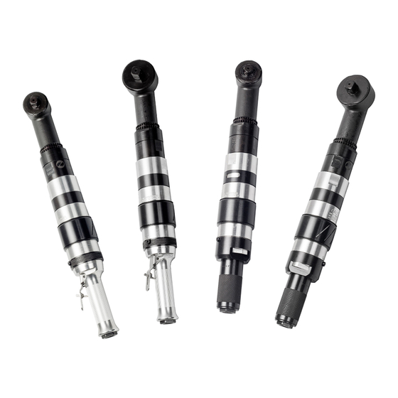
- Page 1 445 Series Motors Models 445L1753-190, 445R1753-190, 445L1752-90, 445R1752-90 Tube & Pipe Cleaners Tube Testers Tube Plugs Tube Removal Tube Installation Operating and Maintenance Instructions www.elliott-tool.com...
- Page 2 This page intentionally left blank.
-
Page 3: Table Of Contents
Table Of Contents Introduction ......................4 Safety Instructions ....................5 Operating Instructions ..................8 Maintenance Instructions ................... 11 Technical Specifications ..................12 Technical Drawings .................... 13 Warranty ......................21... -
Page 4: Introduction
Introduction Thank you for purchasing this Elliott product. More than 100 years of experience have been employed in the design and manufacture of our products, representing the highest standard of quality, value and durability. Elliott tools have proven themselves in thousands of hours of trouble free field operation. -
Page 5: Safety Instructions
Safety Instructions Read and save all instructions. Before use, be sure everyone that will operate this tool reads and understands this manual, as well as any labels packaged with or attached to the tool. Impact-resistant eye protection must be worn while WARNING operating or working near this tool. - Page 6 Safety Instructions (cont.) • Always wear protective clothing, safety boots, gloves, dust mask, etc, when operating or in an area where the equipment is being used. This prevents crushing, inhalation and skin exposure hazards from the equipment and/or lubricant used in the equipment. •...
- Page 7 Safety Instructions (cont.) WARNING REPETITIVE MOTION: Repetitive work motions and/or vibration can injure hands and arms. Tasks should be performed in such a manner that the wrists are maintained in a neutral position, which is not flexed, hyperextended or turned side to side. Stressful postures should be avoided and can be controlled through tool selection and work location.
-
Page 8: Operating Instructions
Operating Instructions WARNING HIGH TORQUE TOOL: Always use proper reaction bar. NOTE: The reaction bracket, PN: 445-6001, must fully engage the spline on the right angle head. Position the bracket forward on the small diameter of the head and then move it rearward to engage the spline. - Page 9 Operating Instructions (cont.) The Right Angle Rolling Motor is designed to operate on 90 PSI (t2 bar) air pressure using a ½” hose up to 8 ft. in length. The Right Angle Rolling Motors are designed to operate on 90 PSI air pressure, but do not depend on controlled air pressure to maintain accurate torque.
- Page 10 Operating Instructions (cont.) Air Supply An automatic in-line filter-lubricator is highly recommended. This will supply the tool with clean, dry, lubricated air; keep it in sustained operation; and increase tool life. A mesh screen is supplied in the motor to help prevent debris from entering motor. This should be removed and cleaned regularly. For maximum performance, use a ½”...
-
Page 11: Maintenance Instructions
Maintenance Application of the tool should govern how frequently it is checked for maintenance. It is recommended that the right angle gears receive a generous amount of No. 2 moly grease through the grease plug (located on top of right angle head) after 40 hours of operation. A wire mesh screen is included in motor to prevent introduction of large debris particles into the motor. -
Page 12: Technical Specifications
Technical Specifications 445L1753-190** 445R1753-190 445R1752-90 445L1752-90** 2” - 3” 2” - 4” Tube OD Range (50.8 - 76.2mm) (50.8 - 101.6mm) Free Speed RPM 70 - 140 ft lbs 150 - 305 ft lbs Torque Range*** (95 - 190 Nm) (200 - 410 Nm) Weight (With Reaction Bar) -
Page 13: Technical Drawings
Torque Reaction Bar Part Number Description P8296K Hex Head Cap Screw 445-6002 Reaction Bar Clamp P8296J Hex Head Cap Screw 170C Hex Jam Nut 445-6001 Reaction Bar Bracket 445-1700 Torque Reaction Bar 133C Lock Washer Right Angle Rolling Motor tech drawings... - Page 14 Parts List – 90 RPM Head Assembly Part Number Description 445H0090 90 RPM Head 445-5011 Bearing Retainer PC80-6004ZZ Bearing 445-5003-90 90 RPM Gear Set PC80BH-1812 Needle Bearing 445-5001-90 Right Angle Head 445-5007-90 Drive Shaft PC80M-12121 Needle Bearing 41-4534K39 Plug PC80R16ZZ Bearing 445-5005-90 Bearing Cap...
- Page 15 Parts List – 190 RPM Head Assembly Part Number Description 445H0190 190 RPM Head 445-5011 Bearing Retainer PC80-6004ZZ Bearing 445-5003-190 190 RPM Gear Set PC80BH-1812 Needle Bearing 445-5001-190 Right Angle Head 445-5007-190 Drive Shaft PC80M-10121 Needle Bearing 41-4534K39 Plug PC80-6905RS Bearing 445-5005-190 Bearing Cap...
- Page 16 Parts List – Clutch Assembly Part Number Description Part Number Description 445-3000 Clutch Assembly 445-3022 Spring 445-3015 Clutch Housing 445-3005 Clutch Body 445-3011 First Stage Pinion 445-3002 Clutch Cam PC80-6000ZZ Bearing 37-70545 Spring P8375-59 Retaining Ring 37-S-3180 Spring 445-3021 Spring Retainer 445-3001 Plunger 445-3012...
- Page 17 Parts List – Lever Throttle Assembly Part Number Description Part Number Description 445-1200 Lever Throttle Assembly 445-1025 Exhaust Deflector 445-1024 Muffler 445-1201 Lever Handle Body 445-1026 Exhaust Muffler Retainer 445-2000 Air Motor 445-1020 Spacer 539R Shoulder Screw 445-1211 Reversing Ring P8309-24 O’Ring 445-1019...
- Page 18 Parts List – Roll Throttle Assembly Parts List – Roll Throttle Assembly Part Number Description Part Number Description 445-1300 Roll Throttle Handle 445-1024 Muffler 445-1026 Exhaust Muffler Retainer 445-1301 Roll Handle Body 445-1020 Spacer 445-2000 Air Motor 445-1027 Trip Rod 539R Shoulder Screw 445-1313...
- Page 19 Parts List – 90 RPM Gearbox Assembly Part Number Description 445-4000-90 90 RPM Gearbox Assembly 445-4001 Gear Case 445-4005 Second Stage Spider 445-4008 Second Stage Planet Gear P8573-27 Needle Roller 445-4013 Gear Pin 445-4004 First Stage Spider 445-4007 First Stage Planet Gear Parts List –...
- Page 20 Parts List – Air Motor Assembly Part Number Description 445-2000 Air Motor Assembly P8263C Locknut PC80-6000ZZ Bearing 445-2004 Rear Bearing Plate P8382-8 Spring Pin 445-2005 Cylinder 445-2001 Rotor 445-2002-5 Paddle Set 445-2009 Alignment Pin 445-2007 Front Bearing Plate Right Angle Rolling Motor...
-
Page 21: Warranty
Warranty Should any part, of Seller’s own manufacture, prove to have been defective in material or workman- ship when shipped (as determined by Seller), Seller warrants that it will, at its sole option, repair or replace said part f.o.b., point of manufacture, provided that Buyer notifies, in writing, of such defect within twelve (12) months from date of shipment from the manufacturing plant. - Page 22 Contact Us Elliott Tool offers a complete line of precision tube tools to meet your needs. Contact us or your local support. Locally Supported By: Elliott Tool Technologies, Ltd. 1760 Tuttle Avenue Dayton, Ohio 45403-3428 Phone: +1 937 253 6133 • +1 800 332 0447 www.elliott-tool.com/support...
Need help?
Do you have a question about the 445 Series and is the answer not in the manual?
Questions and answers