Carrier 19XR Series Installation, Operating And Maintenance Instructions
Positive pressure storage system 50/60 hz
Hide thumbs
Also See for 19XR Series:
Table of Contents
Advertisement
Installation, Operating, and
Positive pressure storage systems are designed to provide
safe and reliable service when operated within design specifi-
cations. When operating this equipment, use good judgment
and safety precautions to avoid damage to equipment and
property or injury to personnel.
Installation, start-up, and servicing of this equipment can be
hazardous due to system pressures, electrical components,
and equipment location (roofs, elevated structures, etc.). Only
trained, qualified installers and service technicians should
install, start up, and service this equipment.
Be sure you understand and follow the procedures and safety
precautions contained in this guide.
DO NOT VENT refrigerant relief valves within a building. Outlet from
rupture disc or relief valve must be vented outdoors in accordance with
the latest edition of ASHRAE 15 (American Society of Heating,
Refrigeration, and Air Conditioning Engineers). The accumulation
of refrigerant in an enclosed space can displace oxygen and cause
asphyxiation.
PROVIDE adequate ventilation in accordance with ASHRAE 15, espe-
cially for enclosed and low overhead spaces. Inhalation of high concen-
trations of vapor is harmful and may cause heart irregularities,
unconsciousness, or death. Misuse can be fatal. Vapor is heavier than
air and reduces the amount of oxygen available for breathing. Product
causes eye and skin irritation. Decomposition products are hazardous.
DO NOT USE OXYGEN to purge lines or to pressurize a machine for
any purpose. Oxygen gas reacts violently with oil, grease, and other
common substances.
NEVER EXCEED specified test pressures, VERIFY the allowable test
pressure by checking the instruction literature and the design pressures
on the equipment nameplate.
DO NOT USE air for leak testing. Use only tracer gases and dry
nitrogen.
DO NOT VALVE OFF any safety device.
BE SURE that all pressure relief devices are properly installed and
functioning before operating any machine.
DO NOT WELD OR FLAMECUT any refrigerant line or vessel until
all refrigerant (liquid and vapor) has been removed from chiller. Traces
of vapor should be displaced with dry air or nitrogen and the work area
should be well ventilated. Refrigerant in contact with an open flame
produces toxic gases.
DO NOT USE eyebolts or eyebolt holes to rig machine sections or the
entire assembly.
DO NOT work on high-voltage equipment unless you are a qualified
electrician.
DO NOT WORK ON electrical components, including control panels,
switches, starters, or oil heater until you are sure ALL POWER IS
OFF and no residual voltage can leak from capacitors or solid-state
components.
LOCK OPEN AND TAG electrical circuits during servicing. IF
WORK IS INTERRUPTED, confirm that all circuits are deenergized
before resuming work.
AVOID SPILLING liquid refrigerant on skin or getting it into the eyes.
USE SAFETY GOGGLES. Wash any spills from the skin with soap
Manufacturer reserves the right to discontinue, or change at any time, specifications or designs without notice and without incurring obligations.
PC 211
Catalog No. 531-984
Book 2
Tab
5a
Maintenance Instructions
Printed in U.S.A.
Positive Pressure Storage System
and water. If any enters the eyes, IMMEDIATELY FLUSH EYES with
water and consult a physician.
NEVER APPLY an open flame or live steam to a refrigerant cylinder.
Dangerous overpressure can result. When necessary to heat refrigerant,
use only warm (110 F [43 C]) water.
DO NOT REUSE disposable (nonreturnable) cylinders or attempt to
refill them. It is DANGEROUS AND ILLEGAL. When cylinder is
emptied, evacuate remaining gas pressure, loosen the collar and
unscrew and discard the valve stem. DO NOT INCINERATE.
CHECK THE REFRIGERANT TYPE before transferring refrigerant
to the machine. The introduction of the wrong refrigerant can cause
damage or malfunction to this machine.
Operation of this equipment with refrigerants other than those cited
herein should comply with ASHRAE 15 (latest edition). Contact
Carrier for further information on use of this machine with other
refrigerants.
ENSURE that refrigerant is only pumped to or stored in tanks that are
ASME (American Society of Mechanical Engineers) certified for the
pressures appropriate to the refrigerant being handled.
DO NOT ATTEMPT TO REMOVE fittings, covers, etc., while
machine is under pressure or while machine is running. Be sure pres-
sure is at 0 psig (0 kPa) before breaking any refrigerant connection.
CAREFULLY INSPECT all relief devices, rupture discs, and other
relief devices AT LEAST ONCE A YEAR. If machine operates in a
corrosive atmosphere, inspect the devices at more frequent intervals.
DO NOT ATTEMPT TO REPAIR OR RECONDITION any relief
device when corrosion or build-up of foreign material (rust, dirt, scale,
etc.) is found within the valve body or mechanism. Replace the device.
DO NOT install relief devices in series or backwards.
USE CARE when working near or in line with a compressed spring.
Sudden release of the spring can cause it and objects in its path to act as
projectiles.
EQUIPMENT should be operated by certified personnel only.
DO NOT STEP on refrigerant lines. Broken lines can whip about and
cause personal injury and damage to the machine.
DO NOT climb over a machine. Use platform, catwalk, or staging. Fol-
low safe practices when using ladders.
USE MECHANICAL EQUIPMENT (crane, hoist, etc.) to lift or move
inspection covers or other heavy components. Even if components are
light, use such equipment when there is a risk of slipping or losing your
balance.
BE AWARE that certain automatic start arrangements CAN ENGAGE
THE STARTER. Open the disconnect ahead of the starter in addition to
shutting off the machine or pump.
USE only repair or replacement parts that meet the code requirements
of the original equipment.
DOUBLE-CHECK that coupling nut wrenches, dial indicators, or other
items have been removed before rotating any shafts.
DO NOT LOOSEN a packing gland nut before checking that the nut
has a positive thread engagement.
PERIODICALLY INSPECT all valves, fittings, and piping for corro-
sion, rust, leaks, or damage.
DO NOT MIX REFRIGERANT from chillers that use different com-
pressor oils. Compressor damage can result.
Form 19XR-6SI
Pg 1
19XR
50/60 Hz
5-04
Replaces: 19XB-1SI
Advertisement
Table of Contents

Related Manuals for Carrier 19XR Series

Summary of Contents for Carrier 19XR Series
-
Page 1: Safety Considerations
ASHRAE 15 (latest edition). Contact DO NOT VENT refrigerant relief valves within a building. Outlet from Carrier for further information on use of this machine with other rupture disc or relief valve must be vented outdoors in accordance with refrigerants. -
Page 2: Table Of Contents
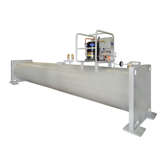
CONTENTS INTRODUCTION Page The 19XR Positive Pressure Storage (PPS) System has been designed to help owners and operators of positive pressure SAFETY CONSIDERATIONS ..... . 1 chillers store HFC-134a refrigerant during service and repair INTRODUCTION . -
Page 3: Mount The Pumpout Unit
Table 1 — Positive Pressure System Assembly Numbers (R-134a) PUMPOUT SYSTEM PUMPOUT UNIT COMPRESSOR MOTOR MAXIMUM ARRANGEMENT STORAGE TANK ASSEMBLY NUMBER (V-Ph-Hz) NUMBER 19XR04027401 19XR04026501 208/230-3-50/60 15.8 105.0 28 cu ft (0.8 cu m) 19XR04027402 19XR04026502 460-3-60 52.0 28 cu ft (0.8 cu m) 19XR04027403 19XR04026503 400-3-50... - Page 4 FRAME TERMINAL SWITCH FUSES ASSEMBLY CONTACTOR STRIP CONTROL PANEL VALVE VALVE VALVE COMPRESSOR HEATER TRANSFORMER VALVE 19XR CONTROL BOX (INTERIOR) ENTERING WATER SEPARATOR LEAVING CONDENSER WATER 19XR PUMPOUT UNIT Fig. 1 — 19XR Positive Pressure Storage System COMPRESSOR CONTROL VALVE ASSEMBLY CONDENSER SEPARATOR...
- Page 5 28.45 (723) 24.75 VAPOR CONNECTIONS (629) 1/2" MALE FLARE VACUUM SWITCH HIGH PRESSURE SWITCH 3.25 WATER CONNECTIONS (83) OIL SEPARATOR 3/4" FNPT COMPRESSOR CONTROL PANEL ELECTRICAL CONNECTION LOCATION 23.00 (584) 18.13 13.12 (461) (333) 11.59 9.74 (294) (247) 8.21 (209) 4.25 (108) 1.00...
-
Page 6: Make Piping Connections
Table 2 — Physical Data — 19XR Pumpout Unit ENGLISH Pumpout Unit Weight* lb (kg) (75) Pumpout Condenser Water Flow Rate gpm (L/s) (.45-.58) Pumpout Condenser Water Pressure Drop psig (kPa) (2.0) Maximum Entering Condenser Water Temperature F (C) (29) Maximum Leaving Condenser Water Temperature F (C) (37) - Page 7 2’-6" 3/8" MALE FLARE [762mm] RELIEF VALVE CONN. 0’-9" LEVEL GAGE [229 mm] 1/2" DIA. K.O. TYPICAL ELECTRICAL CONN. (PUMPOUT POWER) 0’-5 1/2" [140mm] 2’-8 1/2" [826 mm] (2) 1" NPT RELIEF PRESSURE GAGE VALVE OUTLET (SEE FIELD 1’-4 1/4" INSTALLATION NOTES) [413 mm] 1’-7"...
- Page 8 3/8" MALE FLARE 2’- 5 3/4" RELIEF VALVE CONN. [756mm] LEVEL GAGE 0’ - 9 " 1/2" DIA. K.O. [229mm] ELECTRICAL CONN. TYPICAL (PUMPOUT POWER) 0’ - 5 1/2" [140mm] 2’ - 4 3/4 " [730mm] (2) 1" NPT RELIEF 1’...
- Page 9 PRESSURE RELIEF PRESSURE RELIEF TO TOP OF VALVE VALVE CHILLER COOLER OR CONDENSER TO TOP OF CHILLER COOLER PUMPOUT PUMPOUT COMPRESSOR COMPRESSOR SEE NOTE SEE NOTE PUMPOUT SEPARATOR SEPARATOR CONDENSER PUMPOUT TO ADDITIONAL CONDENSER CHILLERS WATER WATER SERVICE VALVES CONNECTIONS SERVICE VALVES CONNECTIONS SEE NOTES...
- Page 10 Table 4 — Relief Devices REQUIRED “C” FACTOR STORAGE RELIEF VALVE TANK SIZE QUANTITY lb air Kg air OUTLET SIZE cu ft (cu m) 1 in. NPT 28 (0.8) 31.4 14.2 Female Connector 1 in. NPT 52 (1.5) 52.3 23.7 Female Connector 2 CL 2 CL...
-
Page 11: Controls And Components
CONTROLS AND COMPONENTS OPERATION Figure 1 shows the major components of the PPS system. Overview — Transferring refrigerant from one vessel to Pumpout Unit — The pumpout unit consists of a another is accomplished by using either gravity or pressure hermetic reciprocating compressor, a water cooled refrigerant differential. -
Page 12: Distilling The Refrigerant
NOTE: During this operation, maintain water circulation FRAME ASSEMBLY through the chiller cooler and condenser vessels to prevent CONTROL PANEL tube freeze-up. DISTILLING THE REFRIGERANT — Refrigerant vapor is transferred from the chiller cooler vessel or pumpout storage tank through the pumpout condenser, condensed to a liquid, and pumped to the chiller condenser vessel. -
Page 13: Tanks
SERVICE VALVE CHILLER CONDENSER VESSEL SERVICE VALVE CHILLER COOLER VESSEL COOLER TEE FOR REFRIGERANT CHARGING PRESSURE ISOLATION RELIEF SAFETY VALVE STORAGE VALVE TANK LIQUID VALVE REFRIGERANT SEPARATOR CHARGING VALVE PUMPOUT PUMPOUT COMPRESSOR CONDENSER SERVICE VALVE ON SERVICE VALVE ON CHILLER (FIELD PUMPOUT PUMPOUT UNIT CONDENSER... -
Page 14: Chillers With Isolation Valves
e. When chiller pressure rises to 40 psig (276 kPa), c. Equalize the refrigerant in the chiller cooler and turn on the pumpout compressor until the pressure condenser. again reaches 35 psig (241 kPa), then, turn off the d. Turn off chiller water pumps and pumpout con- pumpout compressor. -
Page 15: Distilling The Refrigerant
Pumpout Compressor Oil Charge — Use oil con- evacuated chiller vessel to 35 psig (241 kPa). Feed refrig- forming to Carrier specifications for centrifugal or screw com- erant slowly to prevent tube freeze-up. pressor use. Oil requirements are listed in Table 6. -
Page 16: Storage Tank
Ordering Replacement Parts — The following in- or changing oil, relieve the refrigerant pressure through the ac- formation must accompany an order for Carrier-specified parts: cess valves. • machine model number and serial number Relieve refrigerant pressure and add oil to the pumpout unit •...
Need help?
Do you have a question about the 19XR Series and is the answer not in the manual?
Questions and answers