Table of Contents
Advertisement
Advertisement
Table of Contents

Related Manuals for Tunstall Lifeline Smart Hub


Summary of Contents for Tunstall Lifeline Smart Hub
- Page 1 Lifeline Smart Hub & Device Management Platform...
-
Page 3: Table Of Contents
Lifeline Smart Hub & Device Management Platform Contents Contents Contents ......................3 Appendices ......................5 Introduction ..................... 6 Document purpose ........................6 1.1.1 Versions ..................................6 Overview ............................6 1.2.1 Smart Hub communication methods ...........................6 Typographical conventions ......................8 Related documents ........................8 What’s in the Smart Hub box..............9 The Smart Hub .......................... - Page 4 Lifeline Smart Hub & Device Management Platform Contents Configuring the Smart Hub ..............26 Stage 1 – Log on to DMP and access the configuration settings ..........27 Stage 2 – Configure the time zone ................... 30 Stage 3 – Configure speech message settings ................31 Stage 4 –...
-
Page 5: Appendices
Lifeline Smart Hub & Device Management Platform Appendices Appendices Powering down the Smart Hub .............. 60 Smart Hub announcements ..............61 Status of the Smart Hub ................. 65 Applying a template to a device ............. 67 DMP online help ..................69 List of supported triggers/sensors ............ -
Page 6: Introduction
5.4.1. Overview The Lifeline Smart Hub is Tunstall’s latest home unit. Able to communicate using digital (IP) protocols over cellular/mobile networks and fixed line broadband, it opens a new world of possibilities for the provision of care in the home. - Page 7 Domestic broadband connections can be unreliable, especially in the case of a mains power failure to the router/modem. However, cellular services usually remain available, providing the device is within the coverage area of an accessible network. Because of this, Tunstall recommends that you do not rely solely on a domestic Ethernet/fixed broadband connection.
-
Page 8: Typographical Conventions
Lifeline Smart Hub & Device Management Platform Introduction Typographical conventions • Names of fields, buttons, etc. are shown in bold. • References, including those to external documents, are shown in italics. • Links to other sections of the document are shown in teal. -
Page 9: What's In The Smart Hub Box
• a mains power adaptor, along with a with a three metre cable • a user guide, which should be left with the unit. If any of the above is missing, please contact your supplier. The Smart Hub comes with a pre-fitted SIM card, accessing the Tunstall Connectivity communication service. Optional Extras:... -
Page 10: The Smart Hub
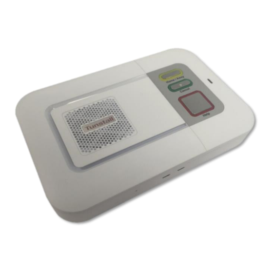
Lifeline Smart Hub & Device Management Platform What’s in the Smart Hub box The Smart Hub 2.1.1 Front/top view Home/Away button (yellow) Speaker Cancel button (green) Status LED (red/green) Cellular signal strength LED Microphone Ethernet connectivity LED Radio antenna Help button (red) 2.1.2 Rear view... -
Page 11: Warning/Status Lights On The Smart Hub
Lifeline Smart Hub & Device Management Platform What’s in the Smart Hub box Warning/status lights on the Smart Hub Home/Away button (yellow) Smart Hub status Away mode Home mode Status LED (green/red) Smart Hub status Green LED on Normal mode... - Page 12 Lifeline Smart Hub & Device Management Platform What’s in the Smart Hub box Cellular Network Signal Strength status The indicated presence of a cellular signal relates to the ability to connect to a network and support a voice/tone connection. There...
-
Page 13: Personal Radio Trigger
Lifeline Smart Hub & Device Management Platform What’s in the Smart Hub box Personal radio trigger TX4 Pendant Wearing Options Wrist Strap Neck Cord When pressed, the red LED on the pendant: • lights up to indicate activation • flashes to indicate that its battery is low •... -
Page 14: Installing The Smart Hub
Lifeline Smart Hub & Device Management Platform Installing the Smart Hub Installing the Smart Hub Before installation, the Smart Hub must be prepared for active use, including: • Within DMP: • moving the device from virtual district “Customer Stock” into the appropriate active district •... -
Page 15: Stage 2 - Connect Leads And Power Up The Smart Hub
Lifeline Smart Hub & Device Management Platform Installing the Smart Hub Stage 2 – Connect leads and power up the Smart Hub 3.2.1 Connect the optional Ethernet cable This is required only if there is to be a fixed line broadband connection. To connect the optional Ethernet cable: 1. -
Page 16: Stage 3 - Check Use Of The Internal Antenna
Acceptable signal Yellow – Light Green 10 to 18 Good signal 19 to 31 Dark Green Strong signal ✍ Tunstall strongly recommend that you consider only ‘Acceptable’, ‘Good’ or ‘Strong’ cellular signal strengths to be sufficient. D5727050C Page 16 of 80... -
Page 17: Stage 5 - Set Up The External Cellular Antenna
Lifeline Smart Hub & Device Management Platform Installing the Smart Hub 5. If using the internal antenna and the cellular signal strength is insufficient: a. Repeat this test in differing locations within the property. Ensure you allow sufficient time, at least 30 seconds, for the LED status indicators to show the change in signal with each move. -
Page 18: Stage 6 - Prepare Sensors For Use As The Virtual Property Exit Sensor
Lifeline Smart Hub & Device Management Platform Installing the Smart Hub • "External antenna selected", switching to using the external antenna is complete • "Internal antenna selected”, repeat step 1 to return to using the external antenna • "Please wait", the unit is unable to process the request immediately, for example, if an alarm call is currently raised. -
Page 19: Stage 7 - Test The Range Of Personal Triggers/Telecare Sensors
Lifeline Smart Hub & Device Management Platform Installing the Smart Hub 6. Register any remaining triggers/sensors by repeating step 3 onwards. If you leave more than 2 minutes between registrations, repeat the process from step 1 as the Smart Hub will have reverted to normal operating mode. -
Page 20: Connect A Hardwired Input Device
Lifeline Smart Hub & Device Management Platform Installing the Smart Hub Once you have connected any required hardwired device, then: • If you need to fix the Smart Hub permanently in position, including its external antenna, or are using a table stand, complete stage 9. -
Page 21: Stage 9 - Fit The Smart Hub In The Required Location
• uses the table stand. If the Smart Hub is to be wall mounted, you can either use the optional Tunstall pattress or fit the unit directly to a wall using the key-slots moulded into the rear of the case. If the Smart Hub is to be placed on a horizontal surface, you can fit it with the optional Tunstall table stand which tilts the unit at an angle and allows for tidy cabling. -
Page 22: Wall Mounting With Pattress
Installing the Smart Hub 3.10.2 Wall mounting with pattress Tunstall is able to supply an optional pattress (part number D5702920) which conceals the cable connections to the unit and allows the unit to be mounted directly to the wall, or onto a recessed electrical back-box. -
Page 23: Wall Mounting Without Pattress
Lifeline Smart Hub & Device Management Platform Installing the Smart Hub 5. Clip the Smart Hub onto the wall pattress, ensuring any cables correctly feed through the pattress back or slot, as required. Images 3a and 3b show how to locate and clip the Smart Hub to the pattress, but for clarity show the unit without either the cabling or the wall. -
Page 24: Fitting The Table Stand
3.10.4 Fitting the table stand Tunstall is able to provide an optional table stand (part number D5702904) which allows the buttons and speaker to be angled towards the user instead of lying flat on a surface. This also covers where cables connect to the unit, which can help to prevent cables from being unplugged. - Page 25 Lifeline Smart Hub & Device Management Platform Installing the Smart Hub 3. Feed the cables through the base of the foot and the large hole in the pattress. See image 3. Connect the cables to the Smart Hub’s sockets. 4. Fit the table stand assembly to the Smart Hub whilst adjusting cables and feeding them back/down as necessary.
-
Page 26: Configuring The Smart Hub
For details of this feature, refer to the Device Management Platform Reference Guide. Tunstall strongly recommends that as much as possible of the configuration is carried out prior to installation, but it is not possible to finalise all of it. As a minimum you need to change those settings that relate to the user’s personal requirements, such as the ringing volume of the unit. -
Page 27: Stage 1 - Log On To Dmp And Access The Configuration Settings
Lifeline Smart Hub & Device Management Platform Configuring the Smart Hub Stage 1 – Log on to DMP and access the configuration settings To log on to DMP and access the configuration settings: 1. Use a recent version of an internet browser such as Edge, Internet Explorer, Safari or Firefox, but preferably Chrome, to access DMP’s web address. - Page 28 Lifeline Smart Hub & Device Management Platform Configuring the Smart Hub 3. Select the Devices menu option, to display the View Devices List page. 4. If you have access to multiple customers and/or districts, select the customer and district containing the device to be configured using the Customer and/or District drop-down lists.
- Page 29 Lifeline Smart Hub & Device Management Platform Configuring the Smart Hub 7. Click the SETTINGS button to open the Device Settings page. This selects the Ringing menu option by default. D5727050C Page 29 of 80...
-
Page 30: Stage 2 - Configure The Time Zone
Lifeline Smart Hub & Device Management Platform Configuring the Smart Hub Stage 2 – Configure the time zone To configure the time zone: 1. Within the Device Settings menu, select the Smart Hub Settings menu option to display: If required, select the correct zone from the Time Zone drop-down list. If a change is made, the field is outlined in red and DMP changes the SAVE button from grey to blue to indicate the pending unsaved changes. -
Page 31: Stage 3 - Configure Speech Message Settings
Lifeline Smart Hub & Device Management Platform Configuring the Smart Hub Stage 3 – Configure speech message settings To configure the speech message settings: 3. Within the Device Settings menu, select the Speech menu option to display: 4. Select the appropriate language from the Language drop-down list. -
Page 32: Stage 4 - Configure Pendant Signalling During An Alarm Call
Lifeline Smart Hub & Device Management Platform Configuring the Smart Hub Stage 4 – Configure pendant signalling during an alarm call This section describes how to indicate whether a client’s pendant can be used to communicate with the responding operator after they have raised an alarm using that pendant. This communication takes the form of audio beeps generated by pressing the pendant. -
Page 33: Stage 5 - Configure Ip Data Communications Settings
Lifeline Smart Hub & Device Management Platform Configuring the Smart Hub Stage 5 – Configure IP data communications settings This section describes how to configure the settings that define IP data communications between the Smart Hub and DMP. Communication may take place using either a fixed-line broadband (Ethernet Interface) or cellular/mobile networks (Cellular IP Interface);... -
Page 34: Stage 6 - Configure Monitoring Centre Settings
Lifeline Smart Hub & Device Management Platform Configuring the Smart Hub Stage 6 – Configure monitoring centre settings This section describes how to configure the settings related to calls made to the monitoring centre. Typically, the configuration of settings relating to monitoring centre call sequences and destinations will have already been applied, so it is unlikely that you need to go through this stage. - Page 35 Lifeline Smart Hub & Device Management Platform Configuring the Smart Hub 2. For each destination you need to specify or update: a. Select the relevant destination, by clicking the appropriate bar containing Destination. DMP displays the related settings. b. If not already specified, enter the Unit ID by which the Smart Hub being installed is known at the monitoring centre destination being configured.
- Page 36 Configuring the Smart Hub • “Telephone Call”, if the destination uses a tone-based signalling protocol • “SMS” if the destination uses Tunstall SMS protocol. d. In the case of an IP destination, update the required attributes as follows: i. Enter the destination monitoring centre’s address either as a numeric IP or a URL, for example, “123.456.789.012”...
-
Page 37: Stage 7 - Register And Configure Personal Triggers And Telecare Sensors
Ensure it is clear if the sequence is not to repeat. ✍ Tunstall recommend that this option is enabled. However, in some cases this may not be possible as this option must conform to national regulations. For example, some countries have regulations preventing automatic telephone connection attempts from repeating an unlimited number of times. - Page 38 Lifeline Smart Hub & Device Management Platform Configuring the Smart Hub 2. For each trigger/sensor listed: a. Click within the grey bar of the sensor line. DMP displays the selected trigger/sensor’s details. This may include additional fields to the ones shown below.
- Page 39 Lifeline Smart Hub & Device Management Platform Configuring the Smart Hub b. Check that the details are correct. c. If required, use the Sensor Location drop-down list to distinguish the trigger/sensor from others of the same type. This can be by location, owner, or appliance/door type. This helps operators to provide the best response to an alarm.
-
Page 40: Stage 8 - Configure The Virtual Property Exit Sensor
Lifeline Smart Hub & Device Management Platform Configuring the Smart Hub Only delete a trigger/sensor after confirming that the identifier on the DMP record ⚠ matches that on the trigger/sensor’s label. Always check afterwards that the correct trigger/sensor has been deleted. -
Page 41: Stage 9 - Configure Ambient Temperature Monitoring
Lifeline Smart Hub & Device Management Platform Configuring the Smart Hub 3. Enter the time period in minutes for which a unit will monitor for a return to the property after detecting an exit, in Absence Period. If the unit has not detected any return by the end of this time period, it raises a ‘PES Client Wandered’... -
Page 42: Stage 10 - Configure Inactivity Monitoring
Lifeline Smart Hub & Device Management Platform Configuring the Smart Hub 2. Use the Enable Temperature Monitoring checkbox to enable/disable this feature, as required. 3. If monitoring is to be restricted to day-time only, ensure the Suppress Temperature Monitoring At Night checkbox is ticked; otherwise ensure it is clear. -
Page 43: Stage 11 - Configure Hardwired Input
Lifeline Smart Hub & Device Management Platform Configuring the Smart Hub 4.11 Stage 11 – Configure hardwired input To configure any hardwired input: 1. Within the Device Settings menu, select the Hardwired Input menu option to display: 2. Select the normal state of the input, either, “Normally Open” or “Normally Closed”, from the Hardwired Input Mode drop-down list. - Page 44 Lifeline Smart Hub & Device Management Platform Configuring the Smart Hub To use the Cancel At Source feature: 1. Within the Device Settings menu, select the Cancel At Source menu option to display: 2. Set the interval between alarm repeats to the desired number of minutes. This would normally be set in accordance with local policy, taking into account the dependency level of the client and the likely time it will take for a carer to attend.
- Page 45 Lifeline Smart Hub & Device Management Platform Configuring the Smart Hub ✍ In the event of multiple alarms being raised concurrently, only the original will generate Cancel At Source repeats until it is manually cancelled. The concurrent alarms will still be raised and need to be closed down by the monitoring centre.
-
Page 46: Stage 13 - Configure Events
For a list of the events and the typical default settings of their attributes, refer to Appendix G, List of typical default Smart Hub event settings. However, Tunstall may deliver Smart Hubs with different defaults according to local requirements, or your organisation may automatically apply a template on receipt of each device which updates this configuration. - Page 47 Lifeline Smart Hub & Device Management Platform Configuring the Smart Hub 2. Select the event to be updated to display its configuration settings. Each event has the same set of attributes, as shown below: 3. Update the drop-down lists and checkboxes, as required. The most common changes you may need to make are: •...
-
Page 48: Stage 14 - Configure Event Suppression
Lifeline Smart Hub & Device Management Platform Configuring the Smart Hub 4.14 Stage 14 – Configure event suppression You can configure the Smart Hub to block a type of event that occurs within a specific time window so that alarms relating to the event are not raised during that period. The types of event that can be blocked are: •... -
Page 49: Stage 15 - Configure The Home Or Away Feature
Lifeline Smart Hub & Device Management Platform Configuring the Smart Hub 4.15 Stage 15 – Configure the Home or Away feature To configure the settings that relate to the Home or Away feature: 1. Within the Device Settings menu, select the Home Or Away Button menu option to display: 2. -
Page 50: Stage 16 - Configure Periodic Calls
Lifeline Smart Hub & Device Management Platform Configuring the Smart Hub 4.16 Stage 16 – Configure periodic calls ✍ Fields relating to periodic calls should not be changed without discussion with your supplier. To configure the settings that relate to periodic calls: 1. - Page 51 Lifeline Smart Hub & Device Management Platform Configuring the Smart Hub c. Select the Periodic Monitoring Profile On Battery menu option to display: d. If required, set the interval in minutes for IP periodic calls whilst the unit is on battery. This should only be done after discussion with your supplier.
- Page 52 Lifeline Smart Hub & Device Management Platform Configuring the Smart Hub 2. If the periodic calls are to be made using GSM telephony (tone protocols): a. Within the Device Settings menu , select the Smart Hub Settings menu option to display: b.
- Page 53 Lifeline Smart Hub & Device Management Platform Configuring the Smart Hub 5. Within the Device Settings menu, select the Event menu option and open the Periodic Call (IP) Event or the Periodic Call (GSM) Event, as appropriate. DMP displays the same fields for each event.
-
Page 54: Stage 17 - Configure Power Fault Monitoring Settings
2. Ensure the Allow Immediate Mains Fail Alarm checkbox is clear, unless the monitoring centre is to be immediately advised of mains power failure. ✍ Tunstall recommend you enable this option only for selected, high-risk clients; otherwise, an area outage may result in the monitoring centre ‘flooding’ with simultaneous calls from devices in the area. -
Page 55: Stage 18 - Configure Line Ringing Settings
Lifeline Smart Hub & Device Management Platform Configuring the Smart Hub 4.18 Stage 18 – Configure line ringing settings To configure the line ringing settings that relate to the calls made to the unit by the monitoring centre or other telecare-related source: 1. -
Page 56: Stage 20 - Save Changes To Dmp
Lifeline Smart Hub & Device Management Platform Configuring the Smart Hub 2. Ensure the Enable Audible Announcement For Software Download and Installation checkbox is clear. 4.20 Stage 20 – Save changes to DMP Once you have completed defining the Smart Hub’s configuration, you then go on to save these changes in the Smart Hub’s DMP record and communicate them to the unit. - Page 57 Lifeline Smart Hub & Device Management Platform Configuring the Smart Hub 2. Check that the changes are correct and complete. 3. If they are not, click CANCEL, make the required changes as described in the previous sections and then repeat this procedure.
-
Page 58: Testing The Installation
Lifeline Smart Hub & Device Management Platform Testing the installation Testing the installation Stage 1 – Test the range of personal triggers/telecare sensors registered using DMP Following the steps described in Section 3.8, Stage 7 – Test the range of personal triggers/telecare sensors, test the range of any trigger/sensor you registered using DMP. -
Page 59: Stage 3 - Test Virtual Property Exit Sensor
Lifeline Smart Hub & Device Management Platform Testing the installation Stage 3 – Test virtual property exit sensor If the installation included the virtual property exit sensor, you go on to test it as follows: 1. Simulate a person leaving the property by each of the doors covered by the virtual sensor and check that the correct alarm is raised in each instance. -
Page 60: A Powering Down The Smart Hub
Lifeline Smart Hub & Device Management Platform Powering down the Smart Hub Powering down the Smart Hub To avoid possible security and safety problems, you must fully power down the Smart Hub unit, both when uninstalling it and prior to transportation. This is because the unit has an internal battery and mobile phone technology which may cause it to make warning and other announcements after it has been uninstalled. -
Page 61: B Smart Hub Announcements
Lifeline Smart Hub & Device Management Platform Smart Hub announcements Smart Hub announcements This appendix lists the announcements that may occur during installation, together with their probable cause and suggested actions. ✍ The unit repeats some critical warning messages until acknowledged. This ensures that the situation is not missed. - Page 62 Lifeline Smart Hub & Device Management Platform Smart Hub announcements Announcement Probable cause and suggested actions Ethernet connection The unit is no longer connected to the router. Check the Ethernet cable failure and router. Ethernet connection The Ethernet connection is restored and the unit can now communicate restored with the router.
- Page 63 Lifeline Smart Hub & Device Management Platform Smart Hub announcements Announcement Probable cause and suggested actions Programming mode Green Cancel button has been used to enter programming mode. This mode allows the range of radio devices to be tested without raising alarms.
- Page 64 Lifeline Smart Hub & Device Management Platform Smart Hub announcements Announcement Probable cause and suggested actions The alarm call An alarm has occurred and the Smart Hub has tried to contact a sequence has ended monitoring centre but not been successful. Press the green Cancel button to acknowledge and stop the message repeating.
-
Page 65: C Status Of The Smart Hub
Lifeline Smart Hub & Device Management Platform Status of the Smart Hub Status of the Smart Hub The main function of DMP is to monitor that devices are functioning correctly. This is done automatically by constantly monitoring for heartbeats from each device. The health of a unit is represented by traffic light icons. - Page 66 Lifeline Smart Hub & Device Management Platform Status of the Smart Hub Heartbeat Meaning This indicates the device has been set to ‘Inactive’ within DMP, that is, has been temporarily taken out of service. D5727050C Page 66 of 80...
-
Page 67: D Applying A Template To A Device
Lifeline Smart Hub & Device Management Platform Applying a template to a device Applying a template to a device To apply a template to a device: 1. Log on to DMP and display the required Smart Hub on the View Devices List page as described in steps 1 to 5 of Section 4.1,... - Page 68 Lifeline Smart Hub & Device Management Platform Applying a template to a device Select the required template and then click APPLY TEMPLATE. Press the device’s green Cancel button to prompt a DMP connection and initiate the download of the template settings.
-
Page 69: Edmp Online Help
Lifeline Smart Hub & Device Management Platform DMP online help DMP online help The online help within DMP is provided by the Albert AI Assistant. You access it by clicking the Help? Button that appears in the bottom right-hand corner of the DMP... -
Page 70: F List Of Supported Triggers/Sensors
Lifeline Smart Hub & Device Management Platform List of supported triggers/sensors List of supported triggers/sensors Note that availability of peripherals may vary by country and permitted radio frequency. • Bath Sensor • Bed/Chair Occupancy Sensor • Bogus Caller Trigger • Carbon Monoxide Detector •... -
Page 71: G List Of Typical Default Smart Hub Event Settings
Lifeline Smart Hub & Device Management Platform List of typical default Smart Hub event settings List of typical default Smart Hub event settings ✍ This section should be considered only as an example. Some default settings may be adapted by territory requirements and any templates which have been applied prior to installation. - Page 72 Lifeline Smart Hub & Device Management Platform List of typical default Smart Hub event settings Event Type ✓ ✓ ✓ ✓ ✓ ✓ TES Temperature Rise Standard None ✓ ✓ ✓ ✓ ✓ ✓ Flood Detector Activation Standard None ✓...
- Page 73 Lifeline Smart Hub & Device Management Platform List of typical default Smart Hub event settings Event Type ✓ ✓ ✓ ✓ ✓ ✓ Epilepsy Sensor Activation Standard None ✓ ✓ ✓ ✓ ✓ ✓ Epilepsy Sensor Other Standard None ✓...
-
Page 74: H Technical Data
3V Lithium (not changeable) with up to 7 year life Cellular: 2G/3G 5 band GSM/GPRS/Edge/UMTS Alarm Protocols Tunstall IPACS, SCAIP Tone: Tunstall TT21 (STMF & DTMF), Tunstall TT92 (STMF & DTMF), BS8521 (DTMF) Environmental Temperature: Operating temperature (to perform to full specification) 0°C to 45°C Storage: 10°C to 50°C... -
Page 75: Technical Details - Australia
3V Lithium (changeable) with up to 5 year life Cellular: GSM/GPRS/Edge/UMTS Alarm Protocols Tunstall IPACS, SCAIP Tone: Tunstall TT21 (STMF & DTMF), Tunstall TT92 (STMF & DTMF), BS8521 (DTMF) Environmental Temperature: Operating temperature (to perform to full specification) = 0°C to 50°C Storage = -10°C to 55°C Humidity:... -
Page 76: I Glossary
Lifeline Smart Hub & Device Management Platform Glossary Glossary Term/Acronym Description Auto Low Battery Auto Presence. Additional check that the trigger/sensor is functioning. When AP is enabled, each trigger/sensor sends an automatic test signal to the Smart Hub at a specified interval. - Page 77 Description Internet Protocol. The communications protocol used for relaying data packets across network boundaries. Its routing function enables internetworking, and essentially establishes the internet. IPACS Independent Protocol for Alarm Communication Systems. Tunstall’s IP protocol. Light-emitting diode Megahertz PC Connect Programming tool used by other Tunstall Lifeline products.
- Page 78 VoIP connections. Temperature Extremes Sensor TT21 A Tunstall tone protocol using DTMF or STMF signalling. TT92 A Tunstall tone protocol using DTMF or STMF signalling. Uniform Resource Locator. Also known as a web address, is a reference to a web resource that specifies its location on a computer network and a mechanism for retrieving it.
-
Page 79: J Contact Details
Lifeline Smart Hub & Device Management Platform Contact details Contact details Australia Belgium Canada Tunstall Australasia Tunstall N.V. Tunstall Canada Inc. Unit 1, 56 Lavarack Ave Rusatiralaan 1 111 Zenway Blvd Eagle Farm 1083 Brussels Unit 6A Queensland 4009 Belgium... - Page 80 Website: www.uk.tunstall.com/monitoring Our policy of continual development means that product specification and appearance may change without notice. Tunstall does not accept any responsibility for any errors or omissions contained in this document. © 2019 Tunstall Group Ltd. ® TUNSTALL and LIFELINE are registered trademarks.
Need help?
Do you have a question about the Lifeline Smart Hub and is the answer not in the manual?
Questions and answers