MicroAir Avionics M760 Install & User Manual
Hide thumbs
Also See for M760:
- Install & user's manual (24 pages) ,
- Installation and user manual (36 pages)

Related Manuals for MicroAir Avionics M760


Summary of Contents for MicroAir Avionics M760
- Page 1 Microair Avionics Pty Ltd Airport Drive Bundaberg Queensland 4670 Australia Tel: +61 7 41 553048 Fax: +61 7 41 553049 e-mail: sales@microair.com.au...
- Page 2 Transceiver’s controls and design features are described and illustrated. Microair reserves the right to amend this manual as required, to reflect any enhancements or upgrades to the M760 Transceiver. © Microair Avionics Pty Ltd Ensure that the M760 transceiver is switched off during engine starting and stopping to avoid damage occurring.
-
Page 3: Table Of Contents
CD LOCKOUT .............................20 VOX................................21 MONITOR SETUP ............................21 NEW MEMORY MODE ..........................22 EDIT MEMORY MODE ..........................22 EXIT MENU..............................23 WIRING DIAGRAM......................24 SPECIFICATIONS M760 P2....................25 10.0 DRILLING TEMPLATE .......................26 11.0 LIMITED WARRANTY ......................27 M760-P Install & User Manual 01R9.doc Page 3 of 28 April, 2009... -
Page 4: Introduction
1.0 INTRODUCTION Thank you for purchasing this Microair product. The M760 is a 760 channel VHF aircraft transceiver, packaged to fit a standard 57mm (2 ¼”) instrument hole. The M760 has been produced in accordance with CASA APMA approval E2000-004. -
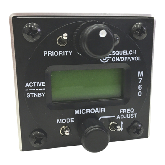
Page 5: Description
M760 Transceiver Installation & User Manual 3.0 DESCRIPTION The M760 VHF Transceiver has a 57mm (2 ¼”) round face to fit a standard small instrument hole. The case is 59mm high x 65mm wide x 135mm long. Front Face Rear Face... -
Page 6: Installation
4.0 INSTALLATION The M760 is very simple to physically install in an aircraft’s instrument panel. Select or cut a 57mm (2 ¼”) instrument hole for mounting. Present the M760 to the rear face of this hole. The stepped round face will insert through the hole, and should appear flush with the front of the instrument panel when correctly positioned. -
Page 7: Electrical Installation
Connect to the rear of the radio with a push fit, and secure the locking bolts (top and bottom). Microair recommends the use of its pre-wired M760 harness. The harness is available from Microair, and comes complete with all switches, sockets, buttons, and mounting hardware. -
Page 8: Coax Termination
ANTENNA For certified aircraft the M760 should only be operated with a TSO compliant antenna. The antenna may be ¼ wave whip or ½ wave dipole, using 50ohm coaxial cable and a BNC connector for connection. The VSWR should ideally be less than 2:1 across the 118.000MHz to 136.975MHz airband. -
Page 9: Power
M760 Transceiver Installation & User Manual POWER The M760 is designed to operate on a 14V aircraft electrical supply. The radio will operate down to 10.7V on receive. It is unlikely that a power supply operating below 11V would have sufficient power to allow clear transmissions. -
Page 10: Microphone
When the PTT is pressed both microphones are live. To reduce background noise, the M760 can be installed with relays across the mic lines and the PTT line, to allow only one microphone at a time to operate. -
Page 11: Internal Vox Intercom
Installation & User Manual INTERNAL VOX INTERCOM The M760 is fitted with a VOX intercom feature which utilises the sidetone facility of the radio. The VOX threshold level is controlled in software by use of the Intercom Adjust Mode. See section 5.4 to adjust the internal VOX intercom. -
Page 12: External Intercom
DUAL COMM INSTALLATION Where two M760’s are to be installed in the aircraft, the interlock lines must be installed. Each interlock line shall be wired from (pin 4) on the first radio to (pin 7) on the second radio, and vice versa. -
Page 13: Operational Controls
Rotate to adjust value Press to move cursor Toggle Switch Momentary push down switch Remote Memory Button Momentary push button Push to talk (PTT) Button Momentary push button M760-P Install & User Manual 01R9.doc Page 13 of 28 April, 2009... -
Page 14: Priority Switch
Transmissions in excess of 30 seconds should be avoided. While the M760 is in the program mode menu or memory programming mode the M760 is in its setup state. The radio can not transmit or receive while it is in the setup state. -
Page 15: Mode Switch
Installation & User Manual MODE SWITCH The mode switch is a push down switch, which will cycle through the operational modes of the M760. When pushed down briefly the radio will step to the next operating mode. Press Mode Key ACTIVE / STANDBY MODE (Refer section 6.1) -
Page 16: Toggle Switch
The M760 will not transmit if the active frequency or selected memory channel is below 118MHz. The M760 will not transmit if the CD lockout function is enabled and the M760 is currently receiving a signal. See section 6.1 to enable / disable the CD lockout function. -
Page 17: Modes
Microair Avionics M760 Transceiver Installation & User Manual 6.0 MODES The M760 transceiver can operate in several operation modes. The user can step through these modes by pressing the mode key briefly. Operational modes are: Active/Standby Mode Channel Mode VOX Mode ACTIVE/STANDBY MODE The display shows the active or in use frequency on the top line. -
Page 18: Monitor Function
NOT monitored. While receiving a signal on the standby frequency the active channel is periodically monitored. If a signal is found on the active frequency the M760 will revert to the active frequency. After a signal has been received the M760 will return to monitoring both frequencies. -
Page 19: Channel Mode
Installation & User Manual CHANNEL MODE The M760 has memory database which can store up to 99 channels. Each channel can be programmed with any available frequency from 108.000 to 136.975MHz, and an 8 character channel name. Refer to the PROGRAM MODE Menu (sections 7.4 & 7.5) for details on the programming of memories. -
Page 20: Programming & Setup
CD LOCKOUT When CD Lockout is set ON the M760 will not permit the PTT button to operate if a radio signal is currently being received. If the user attempts to transmit by keying the PTT, the M760 will not transmit. -
Page 21: Vox
M760 Transceiver Installation & User Manual When VOX setup is set ON the M760 the user is able to set the threshold of the internal VOX intercom via the intercom adjust screen. (See section 6.3) When VOX setup is set OFF the M760 will set the internal VOX intercom to its maximum threshold and disable the Intercom Adjust screen. -
Page 22: New Memory Mode
Rotate the frequency adjust knob to change the character. The word SAVED appears on the bottom line. The M760 will then return to the Program Mode Menu. EDIT MEMORY MODE This option allows the user to program a channel in memory. The frequency and airport code stored in each memory channel can be set, changed, or cleared in this mode. -
Page 23: Exit Menu
Rotate the frequency adjust knob to change the character. The word SAVED appears on the bottom line. The M760 will then return to the Program Mode Menu. To clear a memory, scroll to the desired memory channel and press down the priority switch briefly. The word CLEARED appears on the bottom line. -
Page 24: Wiring Diagram
Microair Avionics M760 Transceiver Installation & User Manual 8.0 WIRING DIAGRAM M760-P Install & User Manual 01R9.doc Page 24 of 28 April, 2009... -
Page 25: Specifications M760P2
Dimensions W-65mm H-59mm D-135mm (plus 35mm for harness) W-2.6” H-2.3” D-5.3” (plus 1.5” for harness) Exposed dial face 57mm diameter 2 ¼” diameter Weight 400 grams 19.4 ounces M760-P Install & User Manual 01R9.doc Page 25 of 28 April, 2009... -
Page 26: Drilling Template
Microair Avionic M760 Transceiver Installation & User Manual 10.0 DRILLING TEMPLATE Drilling Template M760-P Install & User Manual 01R9.doc Page 26 of 28 April, 2009... -
Page 27: Limited Warranty
User and Installation manual(s). It shall be at Microair Avionics sole discretion to decide if a defect is a result of material or workmanship failure. THE WARRANTIES AND REMEDIES CONTAINED HEREIN ARE EXCLUSIVE AND IN LIEU OF ALL... - Page 28 Supplied by:...
Need help?
Do you have a question about the M760 and is the answer not in the manual?
Questions and answers