MicroAir Avionics M760 Install & User's Manual
Hide thumbs
Also See for M760:
- Installation and user manual (36 pages) ,
- Install & user manual (28 pages)

Related Manuals for MicroAir Avionics M760


Summary of Contents for MicroAir Avionics M760
- Page 1 Microair Avionics Pty Ltd Airport Drive Bundaberg Queensland 4670 Australia Tel: +61 7 41 553048 Fax: +61 7 41 553049 e-mail: sales@microair.com.au...
- Page 2 Microair M760 Transceiver. The Transceiver’s controls and design features are described and illustrated. Microair reserves the right to amend this manual as required, to reflect any enhancements or upgrades to the M760 Transceiver. © Microair Avionics Pty Ltd MICROAIR M760 ACCESSORIES...
-
Page 3: Table Of Contents
Microair Avionics M760 Transceiver Installation & User Manual Table of Contents Introduction Unpacking User / Install Manual Warranty Card Authorised Release Certificate Description Installation Physical Installation Electrical Installation Coax Termination Antenna 4.4.1 Metal Skin Airframes 4.4.2 Non-Metal Skin Airframes Backlighting... -
Page 4: Introduction
1.0 Introduction Thank you for purchasing this Microair product. The M760 is a 760 channel VHF aircraft transceiver, packaged to fit a standard 57mm (2 ¼”) instrument hole. The M760 has been produced in accordance with CASA APMA approval E2000-004. -
Page 5: Description
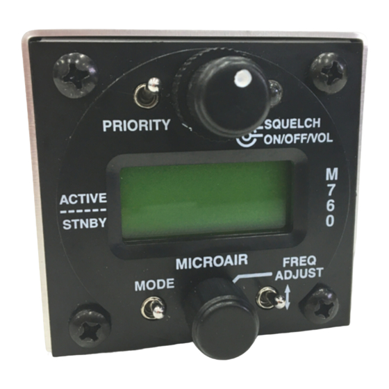
M760 Transceiver Installation & User Manual 3.0 Description The M760 VHF Transceiver has a 57mm (2 ¼”) round face to fit a standard small instrument hole. The case is 59mm high x 65mm wide x 135mm long. Front Face Rear Face... -
Page 6: Installation
4.1 Physical Installation The M760 is very simple to physically install in an aircraft’s instrument panel. Select or cut a 57mm (2 ¼”) instrument hole for mounting. Present the M760 to the rear face of this hole. The stepped round face will insert through the hole, and should appear flush with the front of the instrument panel when correctly positioned. -
Page 7: Electrical Installation
Connect to the rear of the radio with a push fit, and secure the locking bolts (top and bottom). The M760 can be wired in several different configurations, to suit the various needs. The wiring diagrams located in Appendix A cover the most commonly used variations. -
Page 8: Coax Termination
NOT recommended, as their performance is not high enough for VHF transmissions. 4.4 Antenna For certified aircraft the M760 should only be operated with a TSO compliant antenna. The antenna may be ¼ wave whip or ½ wave dipole, using 50ohm coaxial cable and a BNC connector for connection. The VSWR should ideally be less than 2:1 across the 118.000MHz to 136.975MHz airband. -
Page 9: Metal Skin Airframes
Microair Avionics M760 Transceiver Installation & User Manual 4.4.1 Metal Skin Airframes For metal skin aircraft a ¼ wave whip is the easiest antenna to fit. Ensure that the antenna base and the coax shield are firmly grounded to the skin of the airframe, on the inside of the aircraft. Ensure that any anti-corrosion product, which may be used to seal the exterior surface, does not isolate the antenna base from the airframe. -
Page 10: Microphone
When the PTT is pressed both microphones are live. To reduce background noise, the M760 can be installed with relays across the mic lines and the PTT line, to allow on one microphone at a time to operate (refer appendix A). -
Page 11: Intercom
4.9 Intercom The M760 utilises the sidetone facility, to produce a “hot mic” intercom. This means the mic’s are “live” at all times, to the pre-set levels of the sidetone and the mic gain. Both pilot and co-pilot can speak and be heard at all times. -
Page 12: Control Functions
5.2 Volume / Squelch Knob The M760 is turned on, by rotating the volume knob. A positive “click” is heard and felt at the start of the rotation to indicate the on/off position. The volume is increased by rotating the knob clockwise, and decreased by rotating counter clockwise. -
Page 13: Mode Switch
(refer memory programming). 5.4.4 Scan Mode By holding down the toggle switch for 3 seconds, the M760 goes into scan mode. The programmed memories are cycled quickly across the display. The M760 checks each memory in turn for any signal. -
Page 14: Frequency Adjust Knob
Microair Avionics M760 Transceiver Installation & User Manual 5.5 Frequency Adjust Knob The standby frequency can be changed by scrolling the frequency adjust knob. Rotate knob to scroll the MHz half of the standby frequency. Press the knob in briefly to move the cursor to the KHz half of the standby frequency. -
Page 15: Memory Programming
Only programmed memories are displayed. Operating the priority switch in either toggle or memory mode will move the M760 to memory 25. The user should consider carefully what frequency to program in memory 25. The factory default is the distress frequency 121.500MHz. -
Page 16: Operation
If the user elects to operate in memory mode, the remote memory button will step through the programmed memories. If the Remote memory button is held down for 5 seconds, the M760 will go into scan mode, and automatically scroll through the programmed memories, searching for a signal. -
Page 17: Appendix A -Wiring Diagrams
Microair Avionics M760 Transceiver Installation & User Manual 8.0 Appendix A –Wiring Diagrams Standard Wiring Includes remote memory, intercom, and backlighting switches, along with cabin speaker. PTT Operation Include a mode switch to allow the PTT button to be used for either... - Page 18 Microair Avionics M760 Transceiver Installation & User Manual 760 install & user manual ver N Page 18 of 24 December 2003...
- Page 19 Microair Avionics M760 Transceiver Installation & User Manual + 10-16 VOLTS IN GROUND MUSIC GROUND MUSIC SIGNAL 760 install & user manual ver N Page 19 of 24 December 2003...
- Page 20 Microair Avionics M760 Transceiver Installation & User Manual 760 install & user manual ver N Page 20 of 24 December 2003...
-
Page 21: Appendix B - Specifications
Microair Avionic M760 Transceiver Installation & User Manual 9.0 Appendix B - Specifications Specifications Radio Type Amplitude Modulation (AM) Aircraft Transceiver Channels 760 channels, 25KHz spacing 118.000 – 136.975MHz Frequency Selection VFO dial Frequency Display 2 line alpha/numeric LCD display (with backlighting) -
Page 22: Appendix C - Drilling Template
Microair Avionic M760 Transceiver Installation & User Manual 10.0 Appendix C – Drilling Template Drilling Template 760 install & user manual ver N Page 22 of 24 December 2003... -
Page 23: Limited Warranty
Microair may at it discretion, refer product returns for repair or service, to a service facility closest to you. Microair Avionics Pty Ltd reserves the right to repair or replace the unit or software or offer a full refund of the purchase price at it’s sole discretion. - Page 24 Supplied by:...
Need help?
Do you have a question about the M760 and is the answer not in the manual?
Questions and answers