
Related Manuals for MicroAir Avionics M760


Summary of Contents for MicroAir Avionics M760
- Page 1 Microair Avionics Pty Ltd Airport Drive Bundaberg Queensland 4670 Australia Tel: +61 7 41 553048 Fax: +61 7 41 553049 e-mail: sales@microair.com.au...
- Page 2 This is a controlled document and may not be amended, copied or distributed, without the prior consent of Microair Avionics Pty Ltd. © Microair Avionics Pty Ltd Ensure that the M760 transceiver is switched off during engine starting and stopping to avoid damage occurring. CURRENT REVISION STATUS Revision...
-
Page 3: Table Of Contents
Microair Avionics M760 Transceiver Installation & User Manual TABLE OF CONTENTS INTRODUCTION ............................4 UNPACKING.............................. 4 USER / INSTALL MANUAL ..............................4 NAMEPLATE DETAILS................................ 4 AUTHORISED RELEASE CERTIFICATE........................... 4 INSTALLATION ............................5 WIRING ....................................6 COAX TERMINATION ................................. 8 ANTENNA ....................................8 3.3.1... -
Page 4: Introduction
1.0 INTRODUCTION Thank you for purchasing this Microair product. The M760 is a 760 channel VHF aircraft transceiver, packaged to fit a standard 57mm (2 ¼”) instrument hole. The M760 has been produced in accordance with CASA APMA approval E2000-004. -
Page 5: Installation
Installation & User Manual 3.0 INSTALLATION The M760 has a simple physical installation for aircraft instrument panels. Select or cut a 57mm (2 ¼”) instrument hole for mounting (refer panel drilling template in section 9.0). For panel locations which do not afford sufficient space behind the radio to reach the connectors, Microair recommends connecting the wiring harness and coax cable before fitting the radio to the hole in the panel. -
Page 6: Wiring
Microair Avionics M760 Transceiver Installation & User Manual WIRING Microair recommends the use of the wiring in the table below for the various parts of the radio harness: Line Wire Pilot Microphone Tefzel 22 awg single core shielded RS232 RX... - Page 7 (top and bottom). Microair recommends the use of its pre-wired M760 harness. The harness is available from Microair, and comes complete with all switches, sockets, buttons, and mounting hardware.
-
Page 8: Coax Termination
VSWR must be checked to ensure the ratio does NOT exceed 3:1 on 118.000MHz, 127.000MHz, and 136.975Mhz. The M760 will tolerate a VSWR of 5:1 without injury to the transceiver, but the performance is severely deteriorated. Do not use the stubbie “rubber duckie” antennas meant for use with handheld radios. -
Page 9: Metal Skin Airframes
For best performance the whip should be straight and vertical, when mounted on the airframe. Refer to the Microair Avionics website www.microair.com.au for more detail on antennas suitable for metal skin airframes. -
Page 10: Power
M760 Transceiver Installation & User Manual POWER The M760 is designed to operate on a 14V aircraft electrical supply. The radio will operate down to 10.7V on receive. It is unlikely that a power supply operating below 11V would have sufficient power to allow clear transmissions. -
Page 11: Microphone
When the PTT is pressed both microphones are live. To reduce background noise, the M760 can be installed with relays across the mic lines and the PTT line, to allow only one microphone at a time to operate. -
Page 12: Internal Vox Intercom
INTERNAL VOX INTERCOM The M760 is fitted with a VOX intercom feature which utilises the sidetone facility of the radio. The VOX threshold level is controlled in software by use of the VOX Adjust Mode. See section 5.4 to adjust the internal VOX intercom. -
Page 13: External Intercom
Installation & User Manual EXTERNAL INTERCOM Where the M760 is to be installed with an external intercom, the internal VOX intercom should be disabled in the Program Mode Menu. See section 6.2. Wire only a single mic line (pin 1), along with the PTT (pin 7), the headphone (pin 14), and a ground line (pin 11 or 12) to the intercom. -
Page 14: Auxiliary Audio
3.11 AUXILIARY AUDIO The M760 Q can accept a line level audio input via pin 6 of the DB15 connector. The volume of this audio can be set by the auxiliary equipment, but will be muted down to a low level when the VOX intercom is triggered, or a signal is received. -
Page 15: Data Interface (Sl30)
Some types of EFIS equipment do not support SL30 in both directions, ie the user can change channels at the EFIS and the M760 will update, but the user cannot change channels at the radio and have the EFIS update. -
Page 16: Transceiver Function
PC or laptop with a windows operating system (XP or later version). The user can quickly compile channel lists and write them to the M760Q. Refer to the Microair Avionics website for full details of the M760 PC application ( www.microair.com.au... -
Page 17: Noise Suppression
EMI typically affects radio equipment by inducing noise on to the power supply. Microair recommends the installation of a power filter on the power wire to the M760. A simple line filter is sufficient to ensure that the voltage is smooth, and causes no interference to the radio. -
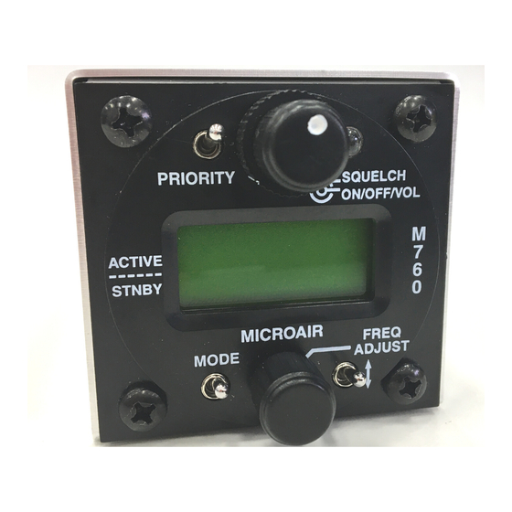
Page 18: Operational Controls
Microair Avionics M760 Transceiver Installation & User Manual 4.0 OPERATIONAL CONTROLS Front Face Control Column ITEM CONTROL DESCRIPTION Priority Switch Momentary push down switch Volume / On / Squelch Click On - Rotate knob for volume Rotate ring for squelch... -
Page 19: Priority Switch
Transmissions in excess of 30 seconds should be avoided. While the M760 is in the program mode menu or memory programming mode the M760 is in its setup state. The radio can not transmit or receive while it is in the setup state. -
Page 20: Mode Switch
Installation & User Manual MODE SWITCH The mode switch is a push down switch, which will cycle through the operational modes of the M760. When pushed down briefly the radio will step to the next operating mode. Press Mode Switch ACTIVE / STANDBY MODE (Refer section 5.1) -
Page 21: Frequency Adjust Knob
Microair Avionics M760 Transceiver Installation & User Manual FREQUENCY ADJUST KNOB The frequency adjust knob is used to change display values and characters. Rotate the knob to scroll values or characters up or down. Press the frequency adjust knob inwards briefly to move the cursor to the next display item to adjust. -
Page 22: Remote Memory Button
Refer to section 5.2 for complete details on monitor function. In channel mode, press the remote memory button briefly to cycle through the stored memory channels. When the M760 is in VOX adjust mode, press the remote memory button briefly to increase the VOX threshold. -
Page 23: Operational Modes
M760 Transceiver Installation & User Manual 5.0 OPERATIONAL MODES The M760 transceiver can operate in several operation modes. The user can step through these modes by pressing the mode switch briefly. Operational modes are: Active/Standby Mode Channel Mode ... -
Page 24: Monitor Function
While receiving a signal on the standby frequency - the active channel is periodically monitored. If a signal is found on the active frequency the M760 will revert to the active frequency. After a signal has been received the M760 will return to monitoring both frequencies. - Page 25 Microair Avionics M760 Transceiver Installation & User Manual Monitor mode can be cancelled by pressing the remote memory button or toggle switch briefly. The ‘M’ character is no longer displayed at the right hand side of the display. If the mode switch is pressed to move from active/standby mode to channel mode, the monitor function is disengaged.
-
Page 26: Channel Mode
Microair Avionics M760 Transceiver Installation & User Manual CHANNEL MODE The M760 has a memory database which can store up to 99 channels. Each channel can be programmed with any available frequency from 108.000MHz to 136.975MHz, and is named with a 4 character location and 3 character service description. -
Page 27: Vox Mode
Microair Avionics M760 Transceiver Installation & User Manual VOX MODE The M760 has a digitally controlled VOX intercom. VOX stands for “voiced activated”, which means the intercom function will trigger automatically when the user starts speaking into the microphone. It is important to set the threshold level to trigger on the microphone. -
Page 28: Program Menu
Installation & User Manual 6.0 PROGRAM MENU The M760 can be started in program mode by holding the mode switch down and turning on. The mode switch must be held down while the display goes through the start-up sequence, and ends with PROGRAM MENU on the display. -
Page 29: Vox
When receiving a signal on the standby channel, the M760 will sample the active channel regularly for signal. The MON value represents the rate of the sample. -
Page 30: New Memory Channel
Microair Avionics M760 Transceiver Installation & User Manual NEW MEMORY CHANNEL This option allows the user to program a new channel into one of 99 memories. The next available memory will automatically be selected. To load a new channel the user must enter the frequency, location, and service type. -
Page 31: Edit Memory Channel
Microair Avionics M760 Transceiver Installation & User Manual EDIT MEMORY CHANNEL The EDIT MEM function allows the user to program a channel in memory. The frequency and airport code stored in each memory channel can be set, changed, or cleared in this mode. -
Page 32: Wiring Diagram
Microair Avionics M760 Transceiver Installation & User Manual 7.0 WIRING DIAGRAM M760Q Install & User Manual 01R12.doc Page 32 of 36 March 2010... -
Page 33: Specifications M760Q
Microair Avionic M760 Transceiver Installation & User Manual 8.0 SPECIFICATIONS M760Q Radio Type Amplitude Modulation (AM) Aircraft Transceiver Channels (Transmit) 760 channels, 25KHz spacing 118.000 – 136.975MHz Channels (Receive) 1160 channels, 25KHz spacing 108.000 – 136.975MHz Frequency Selection VFO dial... -
Page 34: Drilling Template
Microair Avionic M760 Transceiver Installation & User Manual 9.0 DRILLING TEMPLATE Drilling Template M760Q Install & User Manual 01R12.doc Page 34 of 36 March 2010... -
Page 35: Limited Warranty
User and Installation manual(s). It shall be at Microair Avionics sole discretion to decide if a defect is a result of material or workmanship failure. -
Page 36: M760Q Install & User Manual 01R12.Doc
Supplied by:...
Need help?
Do you have a question about the M760 and is the answer not in the manual?
Questions and answers
радиостанция нуждается в ремонте. Куда можно обратиться по поводу ремонта?