Advertisement
INSTALLATION AND MAINTENANCE INSTRUCTIONS
This is a safety alert symbol and should never be ignored. When you see this symbol on labels or in
manuals, be alert to the potential for personal injury or death.
Installation
These units are not approved for mobile home
applications. Such use could result in property damage,
personal injury, or death.
General
These instructions explain the recommended method of
installation of the MGE4 gas heating with electric cooling
unit and associated electrical wiring.
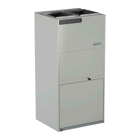
The MGE4 series are self-contained, gas-fired heating with
electric cooling models with optional CLIMATE GUARD™
coated coils. The unit design has been certified by Intertek
Testing Services for compliance with the latest edition of
the American National Standard - ANSI Z21.47/National
Standard of Canada - CAN/CGA-2.3 for direct vent
central furnaces. The MGE4 models are certified to be in
compliance with the latest edition of A.R.I. Standard 390.
All models are design certified for heating operation when
fired with natural or propane gas. Units must be equipped
to use the fuel type provided in the field.
The installation of this appliance must conform to the requirements of the National Fire Protection Association; the National
Electrical Code, ANSI/NFPA No. 70 (latest edition) in the United States; the Canadian Electrical Code Part 1, CSA 22.1
(latest edition) in Canada; and any state or provincial laws or local ordinances. Local authorities having jurisdiction should
be consulted before installation is made. Such applicable regulations or requirements take precedence over the general
instructions in this manual.
507858-01
MGE4 Series
Gas Heating with Electric Cooling Unit
Save these instructions for future reference
WARNING
Table of Contents
Installation ...................................................................1
Start-Up .....................................................................15
Operation ...................................................................15
Maintenance ..............................................................17
Accessories ...............................................................18
Wiring Diagrams ........................................................20
Improper installation, adjustment, alteration, service, or
maintenance can cause injury or property damage. Refer
to this manual. For assistance or additional information,
consult a qualified installer or service agency.
A Lennox International Inc. Company
*P507858-01*
CAUTION
Issue 1922
WARNING
Manufactured By
Allied Air Enterprises LLC
215 Metropolitan Drive
West Columbia, SC 29170
(P) 507858-01
Page 1 of 21
Advertisement

Subscribe to Our Youtube Channel
Related Manuals for Magic-Pak MGE4 Series

Summary of Contents for Magic-Pak MGE4 Series
-
Page 1: Table Of Contents
Refer to this manual. For assistance or additional information, The MGE4 series are self-contained, gas-fired heating with consult a qualified installer or service agency. electric cooling models with optional CLIMATE GUARD™... - Page 2 These instructions, and any instructions packaged with mating components and/or accessories, should be carefully WARNING read prior to beginning installation. Note particularly any CAUTIONS or WARNINGS in these instructions and all The unit must be installed with approved wall sleeve labels on the units.
- Page 3 Clearance to combustible materials is 0” at the side, Top View top, and front of plenum. If accessibility clearances are greater than clearances to combustibles, accessibility clearances take precedence. Return Duct Supply Duct Opening Opening The front of the unit must be accessible for service. If the unit is enclosed, providing a door or access 1"...
- Page 4 NOTE: Platform must be constructed so that it is level with sill plate of wall opening. Figure 2. Wall Sleeve and Louver Kit Installed Location CAUTION WARNING This unit must be installed level to allow for proper drainage of the unit base pan and indoor drain pan. The unit must be installed with approved wall sleeve and grille accessories for safe operation.
- Page 5 Remove the 5/16” screw used to mount the vent pipe For U.S. installations, the vent system shall terminate a minimum horizontal clearance of 4’ from electric assembly to the mounting bracket. Keep this screw. meters, regulators, relief equipment. installations in Canada, refer to the current CAN/ CGA-B149.1 &...
- Page 6 Installing and Securing Unit to Wall Sleeve Five holes have been drilled into the vent extension (see Figure 4). Four of those holes are provided so Before installing and securing the unit to the wall sleeve, that the vent can be extended the necessary length make sure that the proper louver kit is installed.
- Page 7 Ductwork Ductwork should be designed and sized according to the methods in Manual Q of the Air Conditioning Contractors of America (ACCA). Check unit air supply outlet for debris before making ductwork connections. It is recommended that supply and return duct connections at the unit be made with flexible joints.
- Page 8 Gas Heating 0.1 “w.c. 0.2 “w.c. 0.3 “w.c. 0.4 “w.c. 0.5 “w.c. Indoor Rise Blower Range Rise Speed (F°) (F°) TAP 1 (FAN) TAP 2 (COOL)† TAP 3 15 - 45 (COOL) TAP 4 (HEAT)* TAP 5 (HEAT) TAP 1 (FAN) TAP 2 (COOL)†...
- Page 9 Gas Heating 0.1 “w.c. 0.2 “w.c. 0.3 “w.c. 0.4 “w.c. 0.5 “w.c. Indoor Rise Blower Range Rise Speed (F°) (F°) TAP 1 (FAN) TAP 2 (COOL)† TAP 3 15-45 (COOL) TAP 4 (HEAT)* TAP 5 (HEAT) TAP 1 (FAN) TAP 2 (COOL)†...
- Page 10 Gas Heating 0.1 “w.c. 0.2 “w.c. 0.3 “w.c. 0.4 “w.c. 0.5 “w.c. Indoor Rise Blower Range Rise Speed (F°) (F°) TAP 1 (FAN) TAP 2 (COOL)† TAP 3 15-45 (COOL) TAP 4 (HEAT)* TAP 5 (HEAT) TAP 1 (FAN) TAP 2 (COOL)†...
- Page 11 Gas Heating 0.1 “w.c. 0.2 “w.c. 0.3 “w.c. 0.4 “w.c. 0.5 “w.c. Indoor Rise Blower Range Rise Speed (F°) (F°) TAP 1 (FAN) TAP 2 (COOL)† TAP 3 25-55 1030 (COOL) TAP 4 (HEAT)* TAP 5 (HEAT) TAP 1 (FAN) TAP 2 (COOL)†...
- Page 12 Gas Heating 0.1 “w.c. 0.2 “w.c. 0.3 “w.c. 0.4 “w.c. 0.5 “w.c. Indoor Rise Blower Range Rise Speed (F°) (F°) TAP 1 (FAN) TAP 2 1020 (COOL)† TAP 3 25-55 1040 1000 (COOL) TAP 4 (HEAT)* TAP 5 (HEAT) TAP 1 (FAN) TAP 2 1020...
- Page 13 Air Filter All indoor return air must be filtered. A washable filter is furnished with the unit, located in the return air opening. If a filter is installed at a separate central return location, then the factory furnished filter must be removed from the unit. The filter should be cleaned at least three times during each of the heating and cooling seasons, or more frequently if unusual conditions are encountered.
- Page 14 at test pressure equal to or less than 1/2 psig (3.5 kPa) or 14” W.C. If the piping system is to be tested at pressures in WARNING excess of 1/2 psig (3.5 kPa), the furnace and its appliance main gas valve must be disconnected from the gas supply Any conversion of a natural gas unit to propane gas piping system.
-
Page 15: Start-Up
Thermostat To Shut Down Unit The room thermostat should be located on an inside Turn off electrical power to unit. wall where it will not be subject to drafts, sun exposure, Move the gas valve switch to the “OFF” position (see or heat from electrical fixtures or appliances. - Page 16 Adjustments – Heating Section Blower The unit contains a direct-drive, multispeed blower. The Temperature Rise proper speeds have been preset at the factory for typical At time of installation, the temperature rise must be heating and cooling operation. Refer to the wiring diagram adjusted to be within the range specified on the unit rating for recommended heating/cooling speeds for specific plate.
-
Page 17: Maintenance
Make sure there are no leaks of outside air into the Reinstall orifices and burners in the reverse order in return air system. which they were removed. Ensure burners are properly seated over orifices and properly aligned. Keep the outside louver grille as free as possible of any ice that may form and obstruct the flue outlet. -
Page 18: Accessories
Accessories Magic-Pak Unit Dimensions (in) Wall Sleeve Nomenclature for 29” Louver ASLEEVE6-1 • • • • 16-5/8 29-1/8 6” Wall Sleeve Kit for 33” Louver ASLEEVE6-2 • • • • • 32-3/4 16-5/8 32-7/8 for 45” Louver ASLEEVE6-5 • •... - Page 19 Magic-Pak Unit Accessory Nomenclature Polypropylene Louver Kit - White (29” Height / MGE) ALVRPWHTMGE-1 • • • • Polypropylene Louver Kit - White (33” Height / MGE) ALVRPWHTMGE-2 • • • • • Polypropylene Louver Kit - Sandstone (29” Height / MGE) ALVRPSANMGE-1 •...
-
Page 20: Wiring Diagrams
Wiring Diagrams Figure 9. Wiring Diagram - 3/4 Ton through 2 Ton Page 20 of 21 Issue 1922 507858-01... - Page 21 Figure 10. Wiring Diagram - 2-1/2 Ton and 3 Ton 507858-01 Issue 1922 Page 21 of 21...
Need help?
Do you have a question about the MGE4 Series and is the answer not in the manual?
Questions and answers