Table of Contents
Advertisement
Advertisement
Table of Contents

Subscribe to Our Youtube Channel
Related Manuals for Bosch HPC


Summary of Contents for Bosch HPC
- Page 1 Heat Pump Controller Installation, Operation, and Maintenance Manual...
-
Page 2: Table Of Contents
Unit Status LED (Blink Code) Information ...... 20 Heating and Cooling ........... 20 Heartbeat LED............22 Thermistor Resistance Versus Temperature....22 HPC Board Replacement and Installation ......24 Contact Information ........... 24 Recommended Tools..........24 Model and Serial Number..........24 HPC Board Replacement..........24 Wiring Diagrams ...............30... -
Page 3: Document Conventions
Document Conventions | 3 Heat Pump Controller DOCUMENT CONVENTIONS WARNING: This product can expose you to Key to Symbols chemicals including Lead and Lead Warnings components, which are known to the State Warnings in this document are identified by of California to cause cancer and birth a warning triangle printed against a gray defects or other reproductive harm. -
Page 4: Introduction
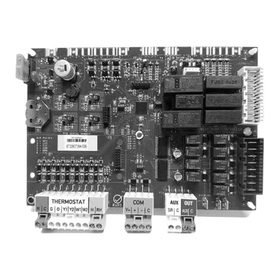
Heat Pump Controller INTRODUCTION Product Description This device provides time delays to prevent the The Heat Pump Controller (HPC) as shown in system from operating under extreme and Fig. 1, is a Printed Circuit Board Assembly (PCBA) potentially hazardous conditions. The HPC... -
Page 5: Bosch Easystart App
• Compressor Stage Two (Y2) signal Field Updates • Electric heat Stage One (W1) signal The HPC software can be updated in the field via the • Electric heat Stage Two (W2) signal Bosch EasyStart app. • Electric heat Emergency (W2/EM) signal •... -
Page 6: Loop Pump Control (Former Pump Valve Relay Kit)
Loop Pump Control (former Pump Valve Relay Kit) A loop pump control relay has been integrated into the HPC board. The loop pump control can be used to energize a field-installed pump or solenoid valve when there is a call for compressor operation. This... -
Page 7: Unit Configuration
Unit Configuration | 7 Heat Pump Controller UNIT CONFIGURATION Settings The Bosch EasyStart app is used to configure available features of the HPC as follows: HPC Settings Default Settings Freeze Protection Strategy 15°F–26°F 26°F Cooling CFM per TON 300–450 400 CFM/Ton Heating CFM per TON 300–450... -
Page 8: Configurable Hard Lockout
CFM with the verified CFM value and should only pulse the latest fault. Once the latest latch it to 400 Cubic Feet per Minute (CFM)/Ton. fault is cleared, the HPC will pulse for any The controller has a “Most Efficient Mode” remaining faults recorded. -
Page 9: System Operation
Freeze Evaporator Soft Lockout Fault Freeze Coaxial Soft Lockout Fault High-Pressure Soft Lockout Fault If the controller is set to “TEST” mode via Bosch EasyStart app, the safety delays will be reduced Low-Pressure Soft Lockout Fault to 10 seconds. The controller will automatically Table 4 Available Fault Snapshots exit test mode after 20 minutes. -
Page 10: Fan Operation
Auxiliary Heat and a different one for Emergency Heat the two outputs must be HPC will command the Loop Pump (LP) output to terminated on W1 units equipped with one stage energize the pump motor whenever a heating or of electric heat. -
Page 11: Reversing Valve Operation
System Operation | 11 Heat Pump Controller Emergency Heating Mode The Loop Pump output of the HPC will energize the pump directly. 230 VAC to 208 VAC on the HPC Emergency heating mode is an electrical heating pump outputs will be present (voltage dependent feature that is used in place of mechanical heating on supply). -
Page 12: Dehumidification
If the thermostat removes the second-stage demand, the HPC will keep the second stage of compressor enabled until demand NOTICE: Keep the HRP configuration setting is satisfied. -
Page 13: System Protection
If the HPS is repeated until the fault is cleared. The LED will open upon a cooling or heating call, the HPC will only flash one error code until it is cleared. See not energize the compressor output. If the “Clearing a Hard Lockout”... -
Page 14: Brownout Protection
The status LED indicator will flash four times, and The HPC will enter a hard lockout when it senses a the alarm output will pulse four times as well, if condition of no water flow. See “Clearing a Hard configured to do so. - Page 15 Discharge Air Temperature (DAT) Sensor The DAT sensor is installed at the inlet attached to a motor mount (leg) and connected to the HPC. It reads the supplied air temperature to determine whether the unit is operating in the correct state Fig.
- Page 16 In the case of a high LWT, above 125°F for one Heating Mode minute, the HPC will issue a warning and save it to memory. The compressor and loop pump will Low EWT activates the LLWPC. Low EWT can only remain running.
- Page 17 Bosch EasyStart The Freeze Evaporator Coil (FZE) is installed on app. The HPC will issue a warning if the DRT sensor is invalid or not within range (via the live monitor the entering refrigerant pipe after the thermal expansion device and before the air coil.
- Page 18 The minimum and maximum allowed temperature set points are 110°F and 140°F respectively and can be adjusted via the Bosch EasyStart app. The controller will run the pump four times/hour (adjustable two to six times/hour via Bosch EasyStart app) to determine whether or not domestic hot water production is needed.
-
Page 19: Troubleshooting
The Blower Motor is a PWM signal that varies from 0 to 24 VDC. The voltmeter will show values from 0 through 24 VDC. Test Mode will be available for 20 minutes. The HPC will enter test mode when commanded via the Bosch EasyStart app. -
Page 20: Unit Status Led (Blink Code) Information
LED is flashing two times a Normal HPC Operation. second LED is flashing at a slow HPC application program is not running. rate, one flash per second Connect to Bosch EasyStart app to instead of two update or reload application. - Page 21 LPS STATUS LED FAULT CODE 2 Check charge and start-up water flow. Compressor pump down at LOW PRESSURE Use the Bosch EasyStart app to verify start-up LOSS OF CHARGE that there are no water flow warnings. Table 8 Troubleshooting HTG-CLG...
-
Page 22: Heartbeat Led
If during an HPC firmware update and there is an update failure (e.g., caused by a power outage), the control software on the HPC will be corrupted. - Page 23 Troubleshooting | 23 Heat Pump Controller Thermistor Resistance Versus Temperature—US SENSOR 10K C° F° C° F° C° F° C° F° 963,800 52,410 6,015 1,141 895,300 49,660 5,774 1,105 832,100 47,070 5,545 1,071 776,800 44,630 5,326 1,038 719,900 42,330 5,116 1,006 670,200 40,160 4,916...
-
Page 24: Hpc Board Replacement And Installation
Fig. 14 Electrical Access Panel Removed of your appliance. 2. Identify the standard harnesses connected to the HPC, as show below, and detach it from the controller. Fig. 13 Example of a Unit Data Plate The controller will not operate the unit without the unit model or serial number. - Page 25 HPC Board Replacement and Installation | 25 Heat Pump Controller 3. Move the plugs to the side to allow room to 5. Once the controller is detached, place the new access the standoffs and the ground screw. controller in the existing footprint.
- Page 26 26 | HPC Board Replacement and Installation Heat Pump Controller 9. Reconnect all the wiring harnesses. Fig. 22 Legal Information Fig. 20 Wiring Harnesses Reconnected 10. Apply power to the unit from the home’s circuit breaker panel. 11. Once the board has been replaced, it will now need to be updated with the latest firmware Fig.
- Page 27 HPC Board Replacement and Installation | 27 Heat Pump Controller 4. In order to connect to the appliance, click the 7. Select the network. Connect to Unit button shown in Fig. 25. The 8. Next select the connection method—either Connect to unit via Wi-Fi screen displays. The...
- Page 28 28 | HPC Board Replacement and Installation Heat Pump Controller Fig. 28 Navigating to User Information Fig. 30 Firmware Update 12. Select the version you want to use [1] from the Extended Menu button list then click the Flash button [2]. The Information Firmware Update progress is displayed.
- Page 29 HPC Board Replacement and Installation | 29 Heat Pump Controller 15. Click Configure Unit Settings. The Configure 18. Click OK [1] to write the configuration to the Unit Settings screen displays. See the list of unit. Once this is completed, your controller unit settings in the figure below.
-
Page 30: Wiring Diagrams
30 | Wiring Diagrams Heat Pump Controller WIRING DIAGRAMS Fig. 36 One Stage (2-Step) Single-Phase Unit with EON Motor FOR REFERENCE ONLY Actual unit wiring may vary from this example. Always refer to the wiring diagram attached to the unit. 8733819577 (2019/02) Subject to change without prior notice Heat Pump Controller... - Page 31 Wiring Diagrams | 31 Heat Pump Controller Fig. 37 One Stage (2-Step) Single-Phase Unit with EON Motor and Electric Heat FOR REFERENCE ONLY Actual unit wiring may vary from this example. Always refer to the wiring diagram attached to the unit. Heat Pump Controller Subject to change without prior notice 8733819577 (2019/02)
-
Page 32: Electrical Box
32 | Electrical Box Heat Pump Controller ELECTRICAL BOX Typical Layout Fig. 38 Typical Electrical Box Layout 8733819577 (2019/02) Subject to change without prior notice Heat Pump Controller... -
Page 33: Thermostat Connections
The HPC is equipped with a standard coded Thermostat interface connectors. Refer to the figures below. Fig. 41 Alarm Terminal Connectors on the HPC Board Fig. 39 HPC Thermostat Connectors Fig. 42 Generic Thermostat Connections Fig. 43 Alarm Support for Dry Contact Thermostats Fig. -
Page 34: Terminology
Decommissioning — Means the final shut-down and HP — Heat Pump removal from operation or usage of a product or piece of equipment containing fluorinated greenhouse gases. HPC — Heat Pump Controller Discharge Pressure — Referring to the pressure leaving HPEEPROM — Heat Pump Electrically-Erasable compressor Programmable Read-Only Memory Reclamation —... -
Page 35: Decommissioning Information
Decommissioning Information | 35 Heat Pump Controller Components DECOMMISSIONING INFORMATION Many parts in the Heat Pump can be fully Only trained and qualified technicians are allowed recycled at the end of the product life. Contact to decommission and dispose of equipment your city authorities for information about the following the requirements of the Local Authority disposal of recyclable products. -
Page 36: Check-Out Sheet
36 | Check-Out Sheet Heat Pump Controller CHECK-OUT SHEET Customer Data Customer Name Date Address Phone Unit Number Unit Nameplate Data Unit Make Model Number Serial Number Refrigerant Charge (oz) Compressor: RLA Blower Motor: FLA (or NPA) Maximum Fuse Size (Amps) Maximum Circuit Ampacity Operating Conditions Cooling Mode... -
Page 37: Easystart Check-Out Sheet
EasyStart Check-Out Sheet | 37 Heat Pump Controller EASYSTART CHECK-OUT SHEET EasyStart Configuration Default Value New Value Freeze Protection Strategy 26°F Cooling CFM per TON 400 CFM/Ton Heating CFM per TON 375 CFM/Ton Fan Only CFM reduction Dehumidification CFM reduction Heat Recover Package Disabled Heat Recovery Setpoint... -
Page 38: Notes
38 | Notes Heat Pump Controller NOTES 8733819577 (2019/02) Subject to change without prior notice Heat Pump Controller... - Page 39 Notes | 39 Heat Pump Controller NOTES Heat Pump Controller Subject to change without prior notice 8733819577 (2019/02)
- Page 40 Bosch Thermotechnology Corp. 65 Grove Street, Watertown, MA 02472 Phone: +1 (800) 283-3787 | Fax: +1 (603) 965-7568 www.bosch-climate.us.com Revised 02/19 8733819577...
Need help?
Do you have a question about the HPC and is the answer not in the manual?
Questions and answers