
Related Manuals for Schumacher Mi7


Summary of Contents for Schumacher Mi7
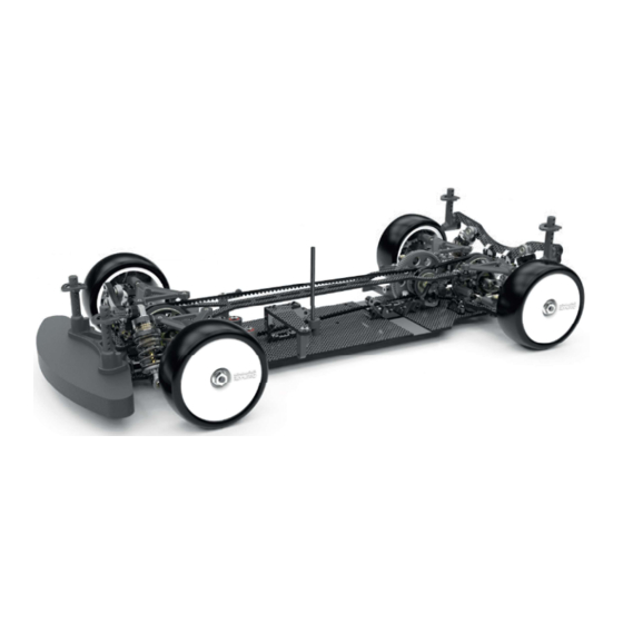
- Page 1 Instruction Manual 71-73 Tenter Road Moulton Park Northampton NN3 6AX U.K. S1497 ISS1...
- Page 2 ADDITIONAL ITEMS REQUIRED Soldering Iron CR266 40w CR275 80w Schumacher Racing stocks and distributes the following manufacturers products and full product listings are U3107 - Solder available on our website at www.racing-cars.com AM701011 - Low Profile 4mm Connector 24K - pk2...
- Page 3 STEP 1 The housings may be a tight fit in the chassis, this is to ensure Black 1.5 mm accurate alignment. ‘B’ ‘A’ Black Ball Stud Short The housings are doweled into the chassis. M3 x 6 STEP 2 ‘B’ The housings may be a tight fit in the chassis, this is to ensure accurate alignment.
- Page 4 STEP 4 M3 x 4 The pulley should spin freely on the shaft. Flanged ø3/16” x ø5/16” The bearings may be a Use the 5.5mm spanner to tight fit on the layshaft. ensure the screw is tight. STEP 5 Ensure fence is assembled as shown.
- Page 5 STEP 7 PIN ASSEMBLY PROCEDURE ø6.4 x ø8.0 x 0.1 Use a small amount of oil to hold all of the parts in place during assembly. Use if needed ø10 x ø15 x 4 SHIM ø5 x ø8 x 2.5 ø5 x ø15 x 0.2 SHIM ø10 x ø12.5 x 0.10...
- Page 6 STEP 10 SHIM ø3.5 x ø9.5 x 0.1 M2.5 x 4 ø2 x ø5 x 1.5 Use a small amount of oil Use 1.6 grams of oil (just to hold all of the parts in covering the bevel gear). place during assembly. STEP 11 M3 x 12 M3 Washer...
- Page 7 STEP 12 Make sure the pips on the eccentric match the image as shown. M3 x 8 The eccentrics are free to rotate. The belt tension will be set later when the top deck is fitted. STEP 13 Ensure fences are assembled as shown.
- Page 8 STEP 15 See Page 5 Step 11 for how to assemble the inserts and dowels. Low Ball Ultra Short Low Ball Short Black 0.5 mm ø3 x ø4 x 3.5 M3 Thread Insert M3 Nut STEP 16 Make sure the pips on the eccentric match the image as shown.
- Page 9 STEP 17 M3 x 6 Make sure you assemble the top deck under the front belt. (see final image). STEP 18 FRONT REAR Tighter belt tension. Tighter belt tension. Looser belt tension. Looser belt tension. Set the eccentric position with the grub screw. IMPORTANT Make sure both sides are set the same and only tighten this grub screw when indents...
-
Page 10: Accurate Alignment
STEP 19 Chamfer this side. The strap may be a tight fit in the chassis, this is to ensure accurate alignment. Black 0.5 mm M3 x 8 STEP 20 Chamfer this side. Chamfer this side. The split blocks may be a tight fit Black 1.0 mm in the chassis, this is to ensure accurate alignment. -
Page 11: Table Of Contents
STEP 22 Assemble the grub screw central to the steering lever. See track settings on how to set this. M3 x 10 ø3.0 x ø4.5 x 0.25 M3 x 6 STEP 23 M3 x 4 ø4 x ø5.65 x 1 Ensure the flats on the steering posts are parallel to the sides of the chassis. - Page 12 STEP 25 Before you assemble M3 Nut the servo horn, connect up your radio gear and set the steering servo to neutral. Black Ball Stud Short 15° SERVO NOT INCLUDED Screw supplied with servo IMPORTANT Select the correct horn for your servo.
- Page 13 STEP 27 - Right Hand Side Front Suspension M3 x 8 Dome Ended M3 x 6 M3 Washer The sphere is on the bottom of the wishbone. IMPORTANT This is the 3 dot wishbone. Set the grub screw Make sure to use the same central for now.
- Page 14 STEP 30 See Page 5 Step 11 for how to assemble the inserts. M3 x 8 Full size front steering arm. M3 Thread Insert Black 1.0 mm Low Ball Ultra Short STEP 31 ø5 x ø7 x 1.5 ø5 x ø10 x 4 ø5 x ø10 x 3 M3 x 2 The flat must face...
- Page 15 STEP 33 - Left Hand Side Front Suspension M3 x 8 Dome Ended M3 x 6 Set the grub screw central for now. M3 Washer See Page 5 Step 11 for how The sphere is to assemble the insert. on the bottom of the wishbone.
- Page 16 STEP 36 See Page 5 Step 11 for how to assemble the inserts. M3 x 8 M3 Thread Insert Full size front steering arm. Black 1.0 mm Low Ball Ultra Short STEP 37 ø5 x ø7 x 1.5 O’ring ø9 x 1.0 ø5 x ø10 x 3 ø1.5 x 9.8 ø5 x ø10 x 4...
- Page 17 STEP 39 IMPORTANT Apply MOLY grease to the blade flats on both sides of the blades. Chamfer this side. M3 x 8 Black 0.5 mm STEP 40 Black 1.5 mm Ball Stud Short To ease assembly insert the ball stud Shorter link into the socket before attaching...
- Page 18 STEP 41 - Right Hand Side Rear Suspension M3 x 6 M3 x 8 Dome Ended Set the grub screw central for now. M3 Washer The sphere is on the bottom of the wishbone. IMPORTANT This wishbone has NO dots. Make sure to use the same wishbone on both sides of the car.
- Page 19 STEP 44 See Page 5 Step 11 for how to assemble the inserts. M3 x 8 M3 Thread Insert Full size rear toe-in arm. Black 0.5 mm Low Ball Ultra Short STEP 45 ø5 x ø7 x 1.5 ø1.5 x 9.8 ø5 x ø10 x 4 O’ring ø9 x 1.0 The flat must face...
- Page 20 STEP 47 - Left Hand Side Rear Suspension M3 x 8 Dome Ended M3 x 6 Set the grub screw central for now. M3 Washer The sphere is on the bottom of the wishbone. IMPORTANT This wishbone has NO dots. M3 Thread Insert Make sure to use the same wishbone on both sides of the car.
- Page 21 STEP 50 See Page 5 Step 11 for how to assemble the inserts. M3 x 8 M3 Thread Insert Full size rear toe-in arm. Black 0.5 mm Low Ball Ultra Short STEP 51 O’ring ø9 x 1.0 ø1.5 x 9.8 ø5 x ø7 x 1.5 Use the hub height setting tool to set the gap between the hub and wishbone.
- Page 22 STEP 53 IMPORTANT Apply MOLY grease to the blade flats on both sides of the blades. Black 1.0 mm M3 x 8 Chamfer this side. STEP 54 Black 1.5 mm Ball Stud Short To ease assembly insert the ball stud into the socket before attaching it to the car.
- Page 23 Car View After Step 54 IMPORTANT Check that all the suspension and steering moves freely with no binding at any point, and make sure the transmission rotates freely. STEP 55 Pivot Ball x 2 Black 2.0 mm M3 x 10 PAGE 22...
-
Page 24: Step
STEP 56 Make sure these two grub screws are tight. M3 x 3 ø1/8” x ø1/4” Push the shock mount down against the ball bearings before tightening the screws. M3 x 10 STEP 57 M3 x 4 M3 x 4 NOTE. - Page 25 STEP 58 Black 1.0 mm M3 x 8 Pivot Ball x 2 STEP 59 Make sure these two grub screws are tight. M3 x 3 ø1/8” x ø1/4” Push the shock mount down against the ball bearings before tightening the screws. M3 x 10 STEP 60 M3 x 4...
- Page 26 MR33 Touring Rear Wing 1mm v2 U7803 C/F Wishbone 54.5mm - Mi7 (pr) MR33-RW2 MR33 Touring Rear Wing 0.7mm v2 U7805 C/F Upper Wishbone Mount 0 Dot - Mi7 (pr) MR-WING MR33 Touring Wing - 1mm U7807 Roll Bar Link Assy - Mi7 (pr) MT010001 Montech - Nazda 6 Body 2.0 - 190mm...
- Page 27 Pinion Gear 64DP 36T (7075 Hard) U7757 Double Joint Driveshaft Tube - V2 CR6437 Pinion Gear 64DP 37T (7075 Hard) U7758 Alloy Trans Housing "A" - Mi7 CR6438 Pinion Gear 64DP 38T (7075 Hard) U7759 Alloy Trans Housing "B" - Mi7 CR6439...
- Page 28 SPARES LIST 3 BEARINGS AND BALLS Cont..PINIONS Cont..U1957 Moly Grease - Pot 5ml CR6458 Pinion Gear 64DP 58T (7075 Hard) U2148 Ball Bearing - 5x10x4 Shield - (pr) CR6459 Pinion Gear 64DP 59T (7075 Hard) U2862 Ceramic Bearing - 5x10x4 Shield - (pr) CR6460 Pinion Gear 64DP 60T (7075 Hard) U3016...
- Page 29 Alloy Radius Arms - Mi7 (pr) U7743 M2.5 X 8 Button Screws (pk10) U7817 C/F Upper Wishbone Mount 1 Dot - Mi7 (pr) U7751 M3x8 Grub Screw Dome End (pk4) U7818 C/F Upper Wishbone Mount 2 Dot - Mi7 (pr) U7774 M3 Alloy Washer Black 1.5 mm (pk10)
- Page 30 EXZES ZZ Radio Set with RX472 G348XXXL Schumacher Arrows" Hoody - XXXL" SA101A32171A MT-44 Radio Set with RX-482 G349L Schumacher Arrows" Zipped Hoody - Large" SA101A32371A M12S-RS Radio Set with RX482 G349M Schumacher Arrows" Zipped Hoody - Medium" SA101A32471A M17 Radio Set with RX491 G349S Schumacher Arrows"...
- Page 31 SPARES LIST 6 BRUSHLESS MOTORS Cont..HW30401109 XERUN-V10-6.5T-Black-G3-BL-Motor HW30401112 XERUN-V10-10.5T-Black-G3-BL-Motor BRUSHLESS ACCESSORIES CONT..HW30401116 XERUN-V10-5T-Black-G3-BL-Motor CR650 90mm Super Flex 26GA Silicone Sensor Wire HW30401117 XERUN-V10-6T-Black-G3-BL-Motor CR651 150mm Super Flex 26GA Silicone sensor Wire HW30401118 XERUN-V10-7T-Black-G3-BL-Motor CR652 125mm Super Flex 26GA Silicone Sensor Wire HW30401130 XERUN-V10-13.5T-Black-G3R-BL-Motor DA770011...
- Page 32 U2100 Set Up Wheels;Camber and Toe In-SST IPCC2S10000HVR LiHV Stick Battery 10000mAh-50C-7.6V U2789 Schumacher Hex Driver - 1.5mm IPCC2S5200HVR LiHV Stick Battery 5200mAh-50C-7.6V 5mm U2790 Schumacher Hex Driver - 2.0mm IPCC2S6000HV4 Intellect Lipo LiHV 120C 2S Hi Power 6000mAh 7.6V U2791 Schumacher Hex Driver - 2.5mm...
- Page 33 SPARES LIST 8 SOREX - TOURING CAR TYRES Cont..XG-28JB Sorex Glued 28R+JB+Revlite24 pk4 XG-28RK Sorex Glued 28R+Black+Revlite 24 - pk4 XG-28RY Sorex Glued 28R+Yellow+ Revlite24 pk4 XG-32JB Sorex Glued 32R+JB+Revlite24 pk4 XG-32RK Sorex Glued 32R+Black+Revlite 24-pk4 XG-32RY Sorex Glued 32R+Yellow+Revlite24 pk4 XG-36RY Sorex Glued 36R+Yellow+Revlite24-pk4 XG-36SR...
- Page 34 STEP 61 Make four shocks the same. The factory setting has two shims here. SHIM 0.05mm O’ring IMPORTANT O-rings must be pre-soaked with shock oil for between 12 to 24 hours prior to assembly, to For better sealing add shims. ensure ideal sealing.
- Page 35 STEP 64 M3 x 12 STEP 65 The bodyposts may be trimmed down for looks and aerodynamics. A sharp knife or side cutters may be used. Alternatively use: AM190041 - Arrowmax - Body Post Trimmer Snap the body washers onto the pins. ø1.5 X 11.8 M3 x 10 M3 x 12...
- Page 36 STEP 67 For greatest durability use a 4mm wide pinion (Core-RC and Schumacher range) M3 x 10 Black 1.0 mm Motor Motor not included not included STEP 68 Transponder Transponder not included not included M3 x 4 M3 x 4...
- Page 37 STEP 69 8.70mm M3 x 6 Black 0.5 mm M3 x 12 Use these two button head screws along with the battery hooks to move the battery left to right on the chassis. Enusre there is always 0.5mm of endfloat. Three LiPo spacers are included in the kit.
- Page 38 STEP 70 M4 Serrated Wheels and tyres are not included in the kit View of finished car PAGE 37...
- Page 39 Track Settings Cell Type 2S Stick Lipo 2S Shorty Lipo Body Height Position The kit allows for the fine adjustment of bodyshell height with the inclusion of three different body washers. These body washers have three incremental steps in height. The one dot washer is the lowest, the three dot washer is the highest.
- Page 40 Track Settings PAGE 39...
- Page 41 A laydown shock offers a softer feel to the driver. Wishbone Shock Mounting Position The Mi7 offers ultimate adjustability with innovative sideways mounted damper ball studs. By adding washers, the car will become stiffer and feel more responsive to driver input, making the car more nervous and difficult to drive.
-
Page 42: Ride Height
Track Settings Optional Ackerman and Lock Setting ACKERMAN LOCK SETTING Reducing the number of washers The grub screw in the radius arms acts as a behind the centre track rod ball stud lock stop. For more lock unscrew the grub will increase the inside wheel angle screw. - Page 43 Wheelbase Wheelbase on the Mi7 can be adjusted in two places. The inboard front and rear pivot pins. Front: Moving the front axle forwards makes the car smoother to drive in the corner.
- Page 44 Flex Options The Mi7 has multiple ways of adjusting flex: Topdeck thickness and cuts, motor mount screw positions, split block or strap wishbone mounting. A flexible car is usually used in low grip conditions. Conversely a stiff car is usually used in high grip conditions Flex along the length of the car can be used to adjust the balance of the car.
- Page 45 X Large G347XXL XX Large G347XXXL XXX LARGE G347XXXXL XXXX LARGE G347XXXXXL XXXXX LARGE G347XXXXXXL XXXXXX LARGE Schumacher Snapback Flatbill Cap - Heather G360 One Size Fits All Schumacher Arrows Polo Shirt G350S Small G350M Medium G350L Large G350XL X Large...
- Page 46 Speed Secrets CR280 - Ti Pro Ball Studs - Short - (pr) CR664 - Alloy Motor Spacer - 1mm - pk2 CR281 - Ti Pro Ball Studs - Ultra Short - (pr) 48DP SPUR GEARS AM348069 - Spur Gear 48p - 69T AM348070 - Spur Gear 48p - 70T CR310 - Alloy Csk Hex Screws M3 x 6 pk10 AM348071 - Spur Gear 48p - 71T...
- Page 47 U7813 - Titanium Wishbone Ball Stud - Mi-7 (pk4) U7824 - Titanium Pivot Ball 5.5mm High (pr) U7817 - C/F Upper Wishbone Mount 1 Dot - Mi7 (pr) U7826 - Alloy Fan Mount - Mi-7 U7818 - C/F Upper Wishbone Mount 2 Dot - Mi7 (pr)
- Page 48 Mid Motor Conversion Instruction Manual 71-73 Tenter Road Moulton Park Northampton NN3 6AX U.K. S1546 ISS1...
- Page 49 Chassis Page 2 - Step 1 U7926 Use the mid motor chassis instead of the rear motor chassis Belts Page 3 - Step 6 3mm wide long belt U7929 U7928 4mm wide short belt Use the 3mm wide long belt on the front and 4mm wide short belt on the rear as shown. PAGE 1...
- Page 50 Topdeck Page 8 - Step 17 U7927 Use the mid motor topdeck instead of the rear motor topdeck LiPo Mounting Page 35 - Step 69 Set the grub screw flush for maximum inboard position. See page 36 for LiPo mounting instructions U7848 11.50mm This dimension is for the...
- Page 51 LiPo Mounting Assembled PAGE 3...
Need help?
Do you have a question about the Mi7 and is the answer not in the manual?
Questions and answers