Table of Contents
Advertisement
Quick Links
Advertisement
Table of Contents

Related Manuals for Uniden AX 144


Summary of Contents for Uniden AX 144
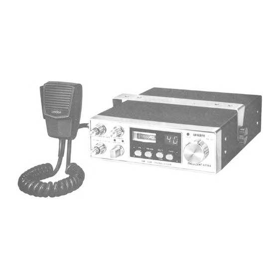
- Page 1 unlden АХ 144 CB RADIO OWNERS MANUAL...
-
Page 2: External Speaker
RADIO BACK PANEL VIEW EXTERNAL SPEAKER Jack IMPORTANT! The above pictorial display shows the location of the various accessory, antenna. and power réceptacles, as well as the SERIAL NUMBER. You are urged to record your model number and your SERIAL NUMBER in the spaces provided below: Model________________ _____________________________ ______________________ SERIAL NUMBER_______________________________________________________... -
Page 3: Specifications
SPECIFICATIONS GENERAL Channels 40 AM, 40 LSB, 40 USB Frequency Range 26.965 to 27.405 MHz Frequency Control Phase Locked Loop(PLL) synthesized circuitry Frequency Tolérance ±0.005% Frequency Stability 0.001% Operating Température Range •10 °C to +50°C Plug-in type; dynamie w ith push-to-talk switch Microphone and coiled cord Input Voltage... - Page 4 RECEIVER SSB: Better than ,25 pV for 10 dB Sensitivity (S+N)/N at greater than ’/a w att of audio output AM: Better than .5 p V for 10 dB (S+N)/N at greater than w att of audio output Selectivity SSB and AM : 6 dB @ 4.2 kHz, 60 dB @ 7.0 kHz Cross Modulation More than 50 dB Image Rejection...
- Page 5 Vour AX 144 is completely factory aligned and quality assurance tested. To obtain the maximum benefit and pleasure from your AX 144 please read very carefully the contents o f this manuał before attempting to install or operate the transceiver.
-
Page 6: Channel Information
CHANNEL INFORMATION Channel Frequency Channel Frequency Channel Channel in MHz in MHz 26.965 27.215 26.975 27.225 26.985 27.255 27.005 27.235 27.015 27.245 27.025 27.265 27.035 27.275 27.055 27.285 27.065 27.295 27.075 27.305 27.085 27.315 27.105 27.325 27.115 27.335 27.125 27.345 27.135 27.355 27.155... -
Page 7: Installation
INSTALLATION Location Plan the location of the transceiver and microphone bracket betöre starting the installation. Select a location that is convenient for operation and does not interfère with the driver or passenger in the vehicle. In automobiles, the transceiver is usually mounted to the dash panel with the microphone bracket beside it. -
Page 8: General Information
This prevents the set being left on accidentally when the driver leaves the car and also permits operating the radio w ithout the engine running. You can locate the accessory contact on most ignition switches by tracing the power wire from the AM broadcast receiver in the car. -
Page 9: Base Station Operation
Mobile whip antennas utilize the metal body of the vehicle as a ground plane. When mounted on a corner of the vehicle, they are slightly directional, in the direction of the body of the vehicle. For all practical purposes, however, the radiation pattern is non-directional. -
Page 10: Operating Controls
The AX 144 is equipped w ith a Clarifier. By tuning the Clarifier, you can slightly change the frequency of the receiver, so you get a normal tone. - Page 11 6. MIKE GAIN: This control is used to adjust, as required, microphone input sensitivity fo r optimum amount o f modulation in transmit UNIDEN's citizen's band transceivers hâve been designed to permit the user to attain levels of modulation up to 100% depending on the setting of the microphone gain control, using the microphone provided with the unit.
-
Page 12: Press To Talk Microphone
INDICATOR FUNCTION S/RF METER: This meter displays relative transmitter RF output power when transmitting, and input signal strength when receiving. The meter is illuminated when power is on, the illumination сап be adjusted by the DIMMER switch for optimum brightness. T X /R X INDICATOR: The T X /R X light in the upper right corner of the front panel lights in red color when the microphone button is pressed and transmitter is in operation. - Page 13 WARNING Operation of this equipment requires a valid station license issued by the Depart ment of Communication Do not transmit w ith your equipment until you hâve a license. - 12 -...
-
Page 14: Maintenance And Adjustment
MAINTENANCE AND ADJUSTMENT This transceiver is especially designed for the environment encountered in mobile installations. The use of all solid state circuitry and its light weight resuit in high reliability. Should failure occur, however, replace parts only with identical parts. Do not substitute. - Page 15 CIRCUIT DIAGRAM FOR AX144 UTUA07524TA Printed in The Philippines...
- Page 16 W ARRANTOR: UNIDEN AUSTRALIA PTY. LTD. 345 Princes Highway, Rockdale, N.S.W . 2216 ("UNIDEN"|. ELEM ENTS OF W AR RA N TY. Uniden Australia warrants, for the duration of this war- ranty, its UNIDEN CB Product to be free from defects in materials and craftsmanship with only the limitation or exclusions set out below.
Need help?
Do you have a question about the AX 144 and is the answer not in the manual?
Questions and answers