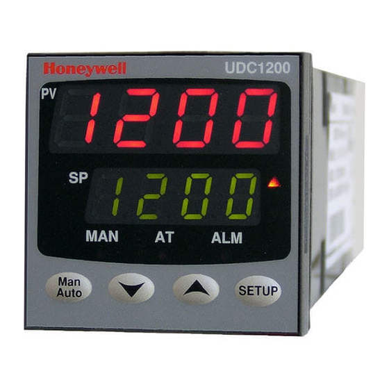
Honeywell UDC1200 MICRO-PRO Startup Manual
Universal digital controller
Hide thumbs
Also See for UDC1200 MICRO-PRO:
- Product manual (2 pages) ,
- Product manual (2 pages) ,
- Startup manual (21 pages)
Advertisement
HONEYWELL UDC1200 MICRO-PRO
HONEYWELL UDC1200 MICRO-PRO
1. Mounting
2. Wiring
3. Select Mode
4. Configuration Mode
5. Setup Mode
6. Operator Mode
7. Automatic Tuning Mode
8. Product Information Mode
9. Installing Option Modules
10. Error Fault Indications
The full users manual can be downloaded from Honeywell IMC Web page
http://content.honeywell.com/imc/
UDC 1200 Start-Up Guide
Universal Digital Controller
Start-Up Guide
HONEYWELL UDC1200 MICRO-PRO
Universal Digital Controller
Page 2
Page 2
Page 3
Page 3
Page 6
Page 7
Page 8
Page 8
Page 9
Page 10
Rev 1
Advertisement
Table of Contents

Related Manuals for Honeywell UDC1200 MICRO-PRO


Summary of Contents for Honeywell UDC1200 MICRO-PRO
- Page 1 8. Product Information Mode Page 8 9. Installing Option Modules Page 9 10. Error Fault Indications Page 10 The full users manual can be downloaded from Honeywell IMC Web page http://content.honeywell.com/imc/ HONEYWELL UDC1200 MICRO-PRO Universal Digital Controller UDC 1200 Start-Up Guide Rev 1...
-
Page 2: Installation
CAUTION: Installation and configuration should be performed only by personnel who are technically competent to do so. Local Regulations regarding electrical installation & safety must be observed. 1. INSTALLATION Panel-Mounting The mounting panel must be rigid and may be up to 6.0mm (0.25 inches) thick. The cut-out required for the instrument is shown on the right. -
Page 3: Select Mode
3. SELECT MODE Select mode is used to access the configuration and operation menu functions. It can be accessed at any time by holding down and pressing Once in select mode, press to select the required mode. An unlock code is required to prevent unauthorised entry to Configuration, Setup &... - Page 4 Parameter Lower Upper Adjustment range Default Display Display Primary Output Reverse Acting Control Action Direct Acting Alarm 1Type Process High Alarm Process Low Alarm Deviation Alarm Band Alarm No alarm ...
- Page 5 Parameter Lower Upper Adjustment range Default Display Display Retransmit Output 1 -1999 to 9999 (display value at which output Range Scale maximum will be maximum) Retransmit Output 1 -1999 to 9999 (display value at which output will Range Scale minimum be minimum)...
-
Page 6: Setup Mode
5. SETUP MODE Note: Configuration must be completed before adjusting Setup parameters. First select Setup mode from Select mode (refer to section 3). While in Setup Mode is lit. Press to scroll through the parameters, then press to set the required value. To exit from Setup mode, hold down and press , to return to Select mode. -
Page 7: Manual Control
This mode is entered at power on. It can also be accessed from Select mode (see section 3). Note: All configuration mode and Setup mode parameters must be set as required before starting normal operations. Press to scroll through the parameters, then press to set the required value. -
Page 8: Product Information Mode
First select Automatic tuning mode from Select mode (refer to section 3). Press to scroll through the modes, then press to set the required value. To exit from Automatic tuning mode, hold down and press to return to Select mode. Pre-tune is a single-shot routine and is thus self-disengaging when complete. -
Page 9: Installing Option Modules
9. Installing Option Modules Installing Option Modules CAUTION: Turn off all power. Remove instrument by gripping the sides of the front panel and pulling the instrument out of its housing. Note its orientation. To access modules 1 or A, first detach the PSU and CPU boards from the front moulding by lifting first the upper, and then lower mounting struts. -
Page 10: Error Fault Indications
10. ERROR/FAULT INDICATIONS Upper Lower Parameter Description Display Display Instrument Configuration & Setup required. Seen at parameters are first turn on or if hardware configuration in default changed. conditions Press to enter the Configuration Mode, next press to enter the unlock code number, then press proceed.
Need help?
Do you have a question about the UDC1200 MICRO-PRO and is the answer not in the manual?
Questions and answers