Table of Contents
Advertisement
INDEX
CHAPTER 2 - ABOUT THE KEYPAD ............................................................................. 2
) ................................................................................................ 2
............................................................................................... 2
............................................................................................... 4
................................................................................................................. 4
3.6 Set date and time .................................................................................................. 5
3.7 Set follow-me numbers ........................................................................................ 6
3.8 Arm and arm sound .............................................................................................. 6
3.9 Disarm and disarm sound .................................................................................... 6
3.10 Duress code disarm ........................................................................................... 7
3.11 Stop siren/bell and stop dialing a number ....................................................... 7
3.12 Bypass and un-bypass zone(s) ........................................................................ 7
3.13 Exit a error operation .......................................................................................... 7
3.14 Keypad alarm ...................................................................................................... 7
3.15 Entry delay and exit delay ................................................................................. 8
3.16 Trouble and display............................................................................................. 8
3.17 Zones characters ................................................................................................ 8
3.19 System Partition and Control ............................................................................ 9
CHAPTER 4 SYSTEM INSTALL EXPLAIN .................................................................. 10
4.1
............................................................................................. 12
................................................................................................. 12
RP248CN User's and Installer's Manual
.................................................. 4
............................................................................... 4
................................................................. 4
........................................................................... 10
....................................................................... 10
: ....................................... 10
.................................................................................. 12
.............................................................................. 12
(
) ...............................................................................................12
V
.........................................................................................12
CHAPTER 5 - FUNCTION AND TECHNICAL DATA ...................................................14
RP248KCL ............................................................................................14
.........................................................................................................17
CHAPTER 6 PROGRAMMING DIRECTION .................................................................18
...............................................................................................18
....................................................................................18
6.5.1 SPECIAL EXPLAIN ..........................................................................................18
6.5.2 SYSTEM PROGRAM ......................................................................................18
6.5.3 Set Zones ..........................................................................................................22
6.5.4 Programmable Utility Output ..........................................................................27
6.5.5 Code Maintenance ...........................................................................................29
6.5.6 Dialer ..................................................................................................................29
6.5.7 Report Code ......................................................................................................31
6.5.8Add Keypad and Module ..................................................................................31
.....................................................................................32
..................................................14
....................................33
Advertisement
Table of Contents

Related Manuals for Roiscok RP248CN


Summary of Contents for Roiscok RP248CN
-
Page 1: Table Of Contents
4.3 M AIN BROAD LAYOUT AND PORT FUNCTION DESCRIPTION 4.5 C .................. 12 ONNECT THE ELEPHONE 4.6 C ................12 ONNECT THE TANDBY ATTERY 4.7C ..................... 12 ONNECT RANSFORMER 4.8 C ....................12 ONNECT IREN RP248CN User’s and Installer’s Manual... - Page 2 Auto disarm [*]+[6]+[6] Auto stay arm [*]+[6]+[7] keypad panic alarm [1]+[2] at least 2 seconds keypad fire alarm [4]+[5] at least 2 seconds keypad special [7]+[8] at least 2 seconds emergency Escape [ESC] RP248CN User’s and Installer’s Manual Page 1...
-
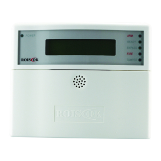
Page 3: Chapter 2 - About The Keypad
CHAPTER 2 – ABOUT THE KEYPAD RP248KCL (LCD Keypad) Fig.1 Layout of the RP248KCL The control panel RP248CN supports LCD Keypad. Each main board can work with 16 LCD Keys Instruction Keypads at most. The keypads display system status by its LED indicators and LCD display. Through its keys, 1-Power LED... - Page 4 [ARM] can be used to choice the month, weekday and partition. CMS or following-me numbers. 10. Keypad Buzzer The buzzer is used for indicating the entry/exit delay, alarm, door chime and so on. 11. Stay Home Arming [STAY] RP248CN User’s and Installer’s Manual Page 3...
-
Page 5: Depress Keys Audible
Each keypad can emit a continuous brief sound, called as DOOR CHIME. If you set the door The Master Code of RP248CN could be set as four or six digit code. The default master chime function, the keypad will emit a door chime sound when the door or window is opened. -
Page 6: Set Date And Time
The other user s can be deleted in the same way. Entry the [0] [#] to delete this User Code If successful, the keypad will emit a short confirming beep. 3.6 Set date and time Set date: [*]+[6]+[2]+[MASTER CODE]+[MM][DD][YY] RP248CN User’s and Installer’s Manual Page 5... -
Page 7: Set Follow-Me Numbers
(Refer to the chapter 6, section 6.5.6 for detail operation) RP248CN can set several groups of 4 digits or 6 digits code in advance, one of them is When alarm, RP248CN control panel can report the alarm events (burglar alarm, fire alarm, master code, and others for users. -
Page 8: Duress Code Disarm
When operate incorrectly, depress [*] to cancel and then operate again. system will auto return to normal status. 3.14 Keypad alarm Bypass zone(s) RP248CN’s keypad (RP248KCL) has 3 groups of emergency buttons for reporting intrude RP248CN User’s and Installer’s Manual Page 7... -
Page 9: Entry Delay And Exit Delay
Depress [*]+[3] +[1] to check the Every zone of RP248CN can be appoint its character, such as delay zone, instant zone, event detail on the LCD. Depress [←][→] to check last or next event. -
Page 10: System Partition And Control
3.19 System Partition and Control RP248CN has 8 zones which can be operated separately. Disarm partitions system Own multi admin right user code can disarm several partitions at the same time, detail Keypad and partition steps is as follows: Keypad can be appointed to any one or more partitions. Each partition can be set individual input a valid user code;... -
Page 11: Chapter 4 System Install Explain
4.3 Main broad layout and port function description: RP248CN match with ROISCOK detectors, CMS and so on, it can buildup a complete As Figure 2, the function of connection port as following: security system. These security systems can be used to resident and any business users 1-“RED”... - Page 12 27-connect to the anode of standby power supply 28-connect to cathode of standby power supply 29/30-“LINE” port of phone line entrance 31/32-“SET”port of user phone 33-alarm dial indicator lamp 34-alarm panel audio transformer RP248CN User’s and Installer’s Manual Page 11...
-
Page 13: Connect The Telephone Line
Please carefully choose a correct transformer to be applicable to AC220V or perhaps AC110V. Remember: The red lines for the high -voltage, do not mix with blue which is the low-voltage. Don't power the system before the installation finished well. RP248CN User’s and Installer’s Manual Page 12... - Page 14 S1---- Connect red wire to “UO” port of the RP248MB Connect black wire to ”COM” of the RP248MB The port beside the S1----Connect to Buzzer of the RP248MB. Anode(Red wire), Cathode (Black wire). RP248CN User’s and Installer’s Manual Page 13...
-
Page 15: Chapter 5 - Function And Technical Data
You can communicate your RP248CN (8-72 zones control panel) through LCD Keypads Quick arm (RP248KCL). Each RP248CN can match with 16 LCD keypads at most. With the LCD Quick arm by code Keypad(s), you can operate your system by arm/disarm, bypass, emergency, closing the ... - Page 16 2—“BLK” connect to BLK on the main board 3—“YEL” connect to YEL on the main board 4—“GRN” connect to GRN on the main board 5—“S.AUX” connect to the DC12V switch power port (S.AUX) on the main board. RP248CN Users and Installer’s Manual Page 15...
- Page 17 Build-in digital communicator and compatible with Contact ID,4+2 System clock is not set 8 follow-me phone numbers Tamper prevention 3 central station numbers Fire alarm loop trouble RP248CN Users and Installer’s Manual Page 16...
-
Page 18: Technical Data
The UO port will be triggered when an alarm occurs, or the system is armed/ disarmed. The Dimension/weight: 201x100x65mm/258g RP248CN can expand to 32 open collector utility output. About the details, please refer to the location 22 of chapter 5. -
Page 19: Chapter 6 Programming Direction
Otherwise, operate as following. CHAPTER 6 PROGRAMMING DIRECTION RP248CN will indicate the operation with the menu on the LCD keypad. If the screen 6.1 Programmable Items indicate “To Install depress *”, please depress [*]. Then, the keypad will indicate you to input RP248CN’s menu indicates the user functions and programming via LCD keypad. - Page 20 Quick BYPS code interference signal which have NO: should enter a code to inspected bypass a zone False code trouble: [2][0][5] FLS CD TRB YES: report to the central station after enter false code RP248CN Users and Installer’s Manual Page 19...
- Page 21 NO: a report will be sent to the YES: After tamper alarm central station as soon as the [2][1][8] TECH TAMPR ( Tamper LED display by AC in trouble keypad) , must recovery by RP248CN Users and Installer’s Manual Page 20...
- Page 22 If parts have already” arm standard time. automatically”, will disarmed NO : no any flexibility time after input the efficiency user could adjust. code. Will [2][2][2] FORCED KSW YES: In any parts, use key RP248CN Users and Installer’s Manual Page 21...
-
Page 23: Set Zones
WINDOWING central station, only display on Hot Key LCD Display Default Explanation the keypad H:00 [4][1] Window Start Set the start time M:00 H:00 [4][2] Window Stop Set the stop time M:00 RP248CN Users and Installer’s Manual Page 22... - Page 24 No entry delay, it will be which user exit after end of [3][0][5] Instant except zone1 triggered alarm extend time close and zone2 immediately. [3][1][9] LATCH KSW If want to arm or disarm to RP248CN Users and Installer’s Manual Page 23...
- Page 25 Buzzer Only alarm sound triggered Delete a zone and restore it The bell and buzzer will be [9][2] Delete a Zone [4][4] Bell+Buzzer to default, then the zone triggered at the same time RP248CN Users and Installer’s Manual Page 24...
- Page 26 Be sure that the noises or the shocks should be from ZONE= 09 (ALLOC): equipment that can be put 3) ERASE at the right place nearing the sensor; then once the then press [ENTER] noises source is started, RP248CN Users and Installer’s Manual Page 25...
- Page 27 Select Zones again ZONES FOR TEST START TEST AT: 01) NONE HOUR: 00 MIN: 00 According display, Set the first testing press[ENTER], then time hours select 16 most likely form) at this step; RP248CN Users and Installer’s Manual Page 26...
-
Page 28: Programmable Utility Output
Usual Output noises source; then press 6.5.4 Programmable Utility Output [ENTER] UO=02 FOLLOWS: Hot Key Output Instruction 0) NOTHING ault Nothing this display, System Response system events press [1] to select [1][1] Event RP248CN Users and Installer’s Manual Page 27... - Page 29 Panic Follow [2][1][0][6] alarm until the system is (Latched) [3][2] Alarm Follow disarmed. Special UO is activated when medical [3][3] Arm Follow [2][1][0][7] Emergency alarm until the system is armed Code Choose user code RP248CN Users and Installer’s Manual Page 28...
-
Page 30: Code Maintenance
[3][3] 0000 station 3 (4 code) Ii. TO EXIT? N Access and Identify Remote control computer 8. Depress [STAY] turn N to Y, and depress [#] to save when LCD displays: Code communication RP248CN Users and Installer’s Manual Page 29... - Page 31 Default 8 times [7][4][2] BY PARTITION Only call the alarm partition [6][2] Fm RETRIES Re-dial times when follow-me correlative follow-me NO. numbers communication failure [7][4][3] CALL ALL Call all the follow-me NO. (01-15) Alarm Restore RP248CN Users and Installer’s Manual Page 30...
-
Page 32: Report Code
Zone expansion module unused [3][2] UTIL OUTPUT [6][5] Quick arm ZE08 Add 8zones expansion module RP248EZ8 [3][2][1] Tamper [6][6] Force arm [3][2][2] Tamper Restr [6][7] WL BUTTON ARM ZE16 Add 16zones expansion module RP248EZ16 RP248CN Users and Installer’s Manual Page 31... -
Page 33: Communication Protocols
Write or cover the data on the choice Round place, press key [ENTER] Dual Radionics Extended 1400Hz Round BUTT=01 (EMPTY): Dual 2) (RE) WRITE Radionics Extended 2300Hz Round Radionics 1400Hz Parity Erase the Data on the choice place, RP248CN Users and Installer’s Manual Page 32... -
Page 34: Rp248Cn Control Panel Contact Id Reporting Codes
High Temperature (DTMF ,parity) Alarm/Restore DTMF Express 0520 (4+2+parity) Temperature Dissipate Alarm/Restore Airflow Unsteady Alarm 6.7 RP248CN Control Panel Contact ID Reporting Codes Event Reporting Contact ID Special Function Zone Alarm/Disarm Report Urgency Key-depress Alarm Code Urgency Key-depress Restore Entry/Exit Alarm... - Page 35 Central Station. This function is Some protocols have a report code used if the alarm to the VOID REP PRG monitoring station for entering and was activated by mistake 3.VIEW exiting the installer programming. To avoid the RP248CN Users and Installer’s Manual Page 34...
- Page 36 Use to turn OFF a particular Next Arm works for one time only keypad’s internal since the system LCL CHIM OFF sounder for any function involving deletes the setting after it is acted upon. RP248CN Users and Installer’s Manual Page 35...
- Page 37 Printer 1 off Deactivates messages to printer 1 PRINTER CNTRL 3 Printer 2 on Activates printer 2 Printer 2 off Deactivates messages to printer 2 Some systems (defined during ANTI-CODE installation of the RP248CN Users and Installer’s Manual Page 36...
Need help?
Do you have a question about the RP248CN and is the answer not in the manual?
Questions and answers