
Subscribe to Our Youtube Channel
Related Manuals for Alienware Aurora R9


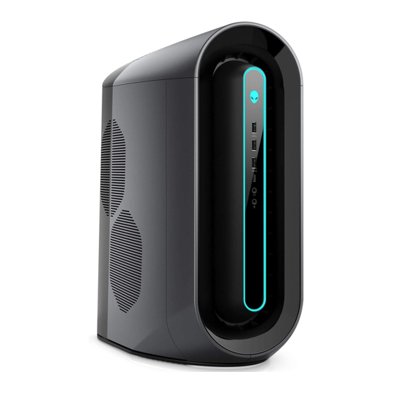
Summary of Contents for Alienware Aurora R9
- Page 1 Alienware Aurora R9 Service Manual Regulatory Model: D23M Regulatory Type: D23M002...
- Page 2 Notes, cautions, and warnings NOTE: A NOTE indicates important information that helps you make better use of your product. CAUTION: A CAUTION indicates either potential damage to hardware or loss of data and tells you how to avoid the problem. WARNING: A WARNING indicates a potential for property damage, personal injury, or death.
-
Page 3: Table Of Contents
Contents 1 Working inside your computer......................6 Safety instructions...............................6 Before working inside your computer..........................6 Before you begin ..............................6 Electrostatic discharge—ESD protection........................6 ESD field service kit ..............................7 Transporting sensitive components..........................8 After working inside your computer..........................8 2 Removing and installing components....................9 Inside view of your computer............................ - Page 4 Installing the right tron-light board........................35 Processor liquid-cooling assembly..........................36 Removing the processor liquid-cooling assembly....................36 Installing the processor liquid-cooling assembly....................38 Coin-cell battery................................ 40 Removing the coin-cell battery..........................40 Installing the coin-cell battery..........................41 Memory modules...............................43 Removing the memory modules.......................... 43 Installing the memory modules..........................44 Solid-state drive................................
- Page 5 Removing the power-button board........................85 Installing the power-button board.........................85 System board................................86 Removing the system board..........................86 Installing the system board..........................88 Entering the Service Tag in the BIOS setup program..................91 3 Device drivers........................... 92 Operating system..............................92 Downloading the audio driver............................92 Downloading the graphics driver..........................92 Downloading the USB driver.............................
-
Page 6: Working Inside Your Computer
Working inside your computer Safety instructions Use the following safety guidelines to protect your computer from potential damage and to ensure your personal safety. Unless otherwise noted, each procedure included in this document assumes that you have read the safety information that shipped with your computer. -
Page 7: Esd Field Service Kit
as intermittent problems or a shortened product life span. As the industry pushes for lower power requirements and increased density, ESD protection is an increasing concern. Due to the increased density of semiconductors used in recent Dell products, the sensitivity to static damage is now higher than in previous Dell products. -
Page 8: Transporting Sensitive Components
• ESD Packaging – All ESD-sensitive devices must be shipped and received in static-safe packaging. Metal, static-shielded bags are preferred. However, you should always return the damaged part using the same ESD bag and packaging that the new part arrived in. The ESD bag should be folded over and taped shut and all the same foam packing material should be used in the original box that the new part arrived in. -
Page 9: Removing And Installing Components
Removing and installing components Inside view of your computer 1. power-supply unit 2. 2.5-inch hard drive 3. 2.5-inch hard-drive cage 4. graphics card 5. system board 6. VR heat sink 7. processor fan and liquid cooling assembly 8. top cover 9. -
Page 10: System-Board Components
System-board components 1. front-chassis fan connector (FRONT_FAN) 2. power-supply connector 3. front-panel USB cable 2 (F_USB2) 4. front-panel USB cable 1 (F_USB1) 5. SATA 6 Gbps drive connector (SATA1) 6. SATA 6 Gbps drive connector (SATA2) 7. SATA 6 Gbps drive connector (SATA3) 8. -
Page 11: Screw List
Screw list NOTE: When removing screws from a component, it is recommended to note the screw type, the quantity of screws, and then place them in a screw storage box. This is to ensure that the correct number of screws and correct screw type is restored when the component is replaced. -
Page 12: Left-Side Cover
Left-side cover Removing the left-side cover Prerequisites 1. Follow the procedure in Before working inside your computer. About this task The following images indicate the location of the left-side cover and provides a visual representation of the removal procedure. Steps 1. -
Page 13: Top Cover
Steps 1. Locate the tabs on the left-side cover and slots on the chassis. 2. Rotate the left-side cover towards the chassis until it snaps into place. 3. Replace the screw (M3x4) that secures the side-cover release latch to the chassis. Next steps 1. -
Page 14: Installing The Top Cover
Steps Starting from the rear, pull up on the top cover to release it from the chassis. NOTE: Top cover is tightly secured to the chassis by clips and may requires force to remove it off the chassis. Installing the top cover Prerequisites If you are replacing a component, remove the existing component before performing the installation procedure. -
Page 15: Right-Side Cover
Steps Align the tabs on the top cover with the slots on the chassis and snap the top cover into place. Next steps 1. Install the left-side cover. 2. Follow the procedure in After working inside your computer. Right-side cover Removing the right-side cover Prerequisites 1. -
Page 16: Installing The Right-Side Cover
Steps 1. Starting from the top-front tab, pull the right-side cover away from the chassis. 2. Remove the right-side cover from the chassis. Installing the right-side cover Prerequisites If you are replacing a component, remove the existing component before performing the installation procedure. About this task The following images indicate the location of the right-side cover and provides a visual representation of the installation procedure. -
Page 18: 2.5-Inch Hard Drive
Steps 1. Align the tabs on the right-side cover with the slots on the chassis 2. Rotate the right-side cover towards the chassis until it snaps into place. Next steps 1. Install the cover. 2. Install the left-side cover. 3. Follow the procedure in After working inside your computer. -
Page 19: Installing The 2.5-Inch Hard Drive
Steps 1. Disconnect the data and power cables from the hard drive. 2. Press the release tabs on the hard-drive carrier and slide the hard-drive assembly out of the hard-drive cage. 3. Pry the hard-drive carrier to release the tabs on the assembly from the slots on the hard drive. 4. - Page 20 NOTE: Note the orientation on the hard-drive carrier to replace it correctly.
-
Page 21: 3.5-Inch Hard Drive
Steps 1. Align the hard drive with the pins on the hard-drive carrier. 2. Using the tabs on the opposite side, flex open the carrier to insert the pins on the other side. 3. Slide the hard-drive assembly into the hard-drive cage until it snaps into place. 4. -
Page 22: Installing The 3.5-Inch Hard Drive
Steps 1. Disconnect the data and power cables from the hard drive. 2. Press the release tabs on the hard-drive carrier and slide the hard-drive carrier out of the hard-drive cage. 3. Pry the hard-drive carrier to release the tabs on the carrier from the slots on the hard drive. 4. - Page 23 NOTE: Note the orientation on the hard-drive carrier to replace it correctly.
-
Page 24: 2.5-Inch Hard-Drive Cage
Steps 1. Align the hard drive with the pins on the hard-drive carrier. 2. Using the tabs on the opposite side, flex open the carrier to insert the pins on the other side. 3. Slide the hard-drive assembly into the hard-drive cage until it snaps into place. 4. -
Page 25: Installing The 2.5-Inch Hard-Drive Cage
Installing the 2.5-inch hard-drive cage Prerequisites If you are replacing a component, remove the existing component before performing the installation procedure. About this task The following images indicate the location of the 2.5-inch hard-drive cage and provides a visual representation of the installation procedure. -
Page 26: Installing The 3.5-Inch Hard-Drive Cage
About this task The following images indicate the location of the 3.5-inch and provides a visual representation of the removal procedure. Steps 1. Remove the two screws (#6-32) that secure the 3.5-inch hard-drive cage to the chassis. 2. Lift the 3.5-inch hard-drive cage off the chassis. Installing the 3.5-inch hard-drive cage Prerequisites If you are replacing a component, remove the existing component before performing the installation procedure. -
Page 27: 460 W Power-Supply Unit
Steps 1. Insert the 3.5-inch hard-drive cage into its slot on the chassis. 2. Align the tabs on the cage with the tabs on the chassis. 3. Replace the two screws (#6-32) that secure the 3.5-inch hard-drive cage to the chassis. Next steps 1. -
Page 29: Installing The 460 W Power-Supply Unit
Steps 1. Remove the two screws (#6-32) that secure the power-supply unit bracket to the power-supply unit cage. 2. Lift the power-supply unit bracket off the power-supply unit cage. 3. Lift the power-supply unit cage and rotate the power-supply unit cage away from the chassis. 4. - Page 30 WARNING: The cables and ports on the back of the power-supply unit are color-coded to indicate the different power wattage. Ensure that you plug in the cable to the correct port. Failure to do so may result in damaging the power- supply unit and/or system components.
-
Page 31: 850 W Power-Supply Unit
Steps 1. Place the power supply on the chassis. 2. Align the screw holes on the power-supply unit with the screw holes on the chassis. 3. Replace the four screws (#6-32) that secure the power-supply unit to the chassis. 4. Lift and rotate the power-supply unit cage away from the chassis 5. -
Page 32: Installing The 850 W Power-Supply Unit
NOTE: Note the routing of all cables as you remove them so that you can route them correctly after you replace the power-supply unit. About this task The following images indicate the location of the power-supply unit and provides a visual representation of the removal procedure. Steps 1. - Page 33 WARNING: The cables and ports on the back of the power-supply unit are color-coded to indicate the different power wattage. Ensure that you plug in the cable to the correct port. Failure to do so may result in damaging the power- supply unit and/or system components.
-
Page 34: Right Tron-Light Board
Right tron-light board Removing the right tron-light board Prerequisites 1. Follow the procedure in Before working inside your computer. 2. Remove the left-side cover. 3. Remove the top-cover. 4. Remove the right-side cover. About this task The following images indicate the location of the right tron-light board and provides a visual representation of the removal procedure. -
Page 35: Installing The Right Tron-Light Board
Installing the right tron-light board Prerequisites If you are replacing a component, remove the existing component before performing the installation procedure. About this task The following images indicate the location of the right tron-light board and provides a visual representation of the installation procedure. -
Page 36: Processor Liquid-Cooling Assembly
Processor liquid-cooling assembly Removing the processor liquid-cooling assembly Prerequisites 1. Follow the procedure in Before working inside your computer. WARNING: Despite having a plastic shield, the processor liquid-cooling assembly may be very hot during normal operation. Ensure that it had sufficient time to cool before you touch it. CAUTION: To ensure maximum cooling for the processor, do not touch the heat transfer areas on the processor liquid-cooling assembly. - Page 37 Steps 1. Lay the computer on the right side. 2. Slide the power-supply unit cage release latches to the unlock position. 3. Lift the power-supply unit cage. 4. Rotate the power-supply unit cage away from the chassis. 5. Loosen the two captive screws that secure the VR heat sink to the system board. 6.
-
Page 38: Installing The Processor Liquid-Cooling Assembly
Installing the processor liquid-cooling assembly Prerequisites If you are replacing a component, remove the existing component before performing the installation procedure. CAUTION: Incorrect alignment of the processor liquid-cooling assembly can damage the system board and processor. About this task The following images indicate the location of the processor liquid-cooling assembly and provides a visual representation of the installation procedure. - Page 39 Steps 1. Slide the radiator and fan assembly into the radiator and fan cage. NOTE: Ensure that the hoses are facing the front of the system 2. Align the screw holes on the processor cooler with the screw holes on the system board. 3.
-
Page 40: Coin-Cell Battery
Coin-cell battery Removing the coin-cell battery Prerequisites 1. Follow the procedure in Before working inside your computer. NOTE: Before working inside your computer, read the safety information that shipped with your computer and follow the steps in Before working inside your computer. -
Page 41: Installing The Coin-Cell Battery
Steps 1. Lay the computer on the right side. 2. Slide the power-supply unit cage release latches to the unlock position. 3. Lift the power-supply unit cage and rotate the power-supply unit cage away from the chassis. 4. Press the battery-release lever away from the coin-cell battery until the coin-cell battery pops up. 5. - Page 42 Steps 1. Insert a new coin-cell battery (CR2032) into the battery socket with the positive side facing up, and snap the battery into place.
-
Page 43: Memory Modules
2. Rotate the power-supply unit cage towards the chassis. 3. Slide the power-supply unit cage release latches towards the locked position. Next steps 1. Install the left-side cover. 2. Follow the procedure in After working inside your computer. Memory modules Removing the memory modules Prerequisites 1. -
Page 44: Installing The Memory Modules
Steps 1. Lay the computer on the right side. 2. Slide the power-supply unit cage release latches to the unlock position. 3. Lift the power-supply unit cage and rotate the power-supply unit cage away from the chassis. 4. Push the securing clips away from the memory module. 5. - Page 45 Steps 1. Ensure that the securing clips are extended away from the memory-module slot.
-
Page 46: Solid-State Drive
2. Align the notch on the memory module with the tab on the memory-module slot. 3. Insert the memory module into the memory-module slot and press the memory module down until it snaps into position and the securing clips lock in place. CAUTION: To prevent damage to the memory module, hold the memory module by the edges. -
Page 47: Installing The Solid-State Drive
Steps 1. Remove the screw (M2x2.5) that secures the solid-state drive to the system board. 2. Slide and lift the solid-state drive off the system board. Installing the solid-state drive Prerequisites If you are replacing a component, remove the existing component before performing the installation procedure. CAUTION: Solid-state drives are fragile. -
Page 48: Single-Graphics Card
Steps 1. Align the notch on the solid-state drive with the tab on the solid-state drive slot. 2. Insert the solid-state drive at a 45-degree angle into the system board. 3. Press the other end of the solid-state drive down and replace the screw (M2x2.5) that secure the solid-state drive to the system board. -
Page 50: Installing The Single-Graphics Card
Steps 1. Lay the computer on the right side. 2. Slide the power-supply unit cage release latches to the unlock position. 3. Lift the power-supply unit cage and rotate the power-supply unit cage away from the chassis. 4. Lift to release the graphics-card bracket from the chassis. 5. -
Page 52: Dual-Graphics Card
Steps 1. Place the card into the X16 slot and press down firmly until the graphics card snaps into place. 2. Connect the power cables to the graphics card. 3. Slide the tab on the graphics-card bracket into the slot on the chassis and rotate it into place. 4. - Page 54 Steps 1. Lay the computer on the right side. 2. Slide the power-supply unit cage release latches to the unlock position. 3. Lift the power-supply unit cage and rotate the power-supply unit cage away from the chassis. 4. Lift the graphics bridge that connects the graphics cards. 5.
-
Page 55: Installing The Dual-Graphics Card
Installing the dual-graphics card Prerequisites If you are replacing a component, remove the existing component before performing the installation procedure. About this task The following images indicate the location of the graphics card and provides a visual representation of the installation procedure. -
Page 57: Front Bezel
Steps 1. Align the graphics card with the slot on the system board. 2. Place the card into the x16/x8 slot and press down firmly until the graphics card snaps into place. 3. Place the card into the x8 slot and press down firmly until the graphics card snaps into place. 4. - Page 58 4. Remove the right-side cover. 5. Remove the single-graphics card dual-graphics card, as applicable. About this task The following images indicate the location of the front bezel and provides a visual representation of the removal procedure.
-
Page 60: Installing The Front Bezel
Steps 1. Lay the computer on the right side. 2. Slide the power-supply unit cage release latches to the unlock position. 3. Lift the power-supply unit cage and rotate the power-supply unit cage away from the chassis. 4. Rotate and pull the front bezel away from the front of the chassis to release the tabs on the front bezel from the slots on the front panel. - Page 61 About this task The following images indicate the location of the front bezel and provides a visual representation of the installation procedure.
- Page 64 Steps 1. Route the cables through the slot on the front panel and align and clip the front bezel into place. 2. Align the screw hole of the cable management cover with the screw hole on the chassis. 3. Replace the two screws (#6-32) that secure the cable management cover to the chassis. 4.
-
Page 65: Top Bezel
Top bezel Removing the top bezel Prerequisites 1. Follow the procedure in Before working inside your computer. 2. Remove the left-side cover. 3. Remove the cover. 4. Remove the right-side cover. 5. Remove the wireless card. 6. Remove the front bezel. -
Page 66: Installing The Top Bezel
Installing the top bezel Prerequisites If you are replacing a component, remove the existing component before performing the installation procedure. About this task The following images indicate the location of the top bezel and provides a visual representation of the installation procedure. Steps 1. -
Page 67: Bottom Cover
Bottom cover Removing the bottom cover Prerequisites 1. Follow the procedure in Before working inside your computer. 2. Remove the left-side cover. 3. Remove the cover. 4. Remove the right-side cover. 5. Remove the 2.5-inch hard-drive cages. 6. Remove the front bezel. -
Page 68: Installing The Bottom Cover
Installing the bottom cover Prerequisites If you are replacing a component, remove the existing component before performing the installation procedure. About this task The following images indicate the location of the bottom cover and provides a visual representation of the installation procedure. Steps 1. -
Page 69: Processor Fan And Heat-Sink Assembly
Processor fan and heat-sink assembly Removing the processor fan and heat-sink assembly Prerequisites 1. Follow the procedure in Before working inside your computer. NOTE: The heat sink may become hot during normal operation. Allow sufficient time for the heat sink to cool before you touch it. -
Page 70: Installing The Processor Fan And Heat-Sink Assembly
Steps 1. Lay the computer on the right side. 2. Slide the power-supply unit cage release latches to the unlock position. 3. Lift the power-supply unit cage and rotate the power-supply unit cage away from the chassis. 4. Disconnect the processor-fan cable from the system board. 5. - Page 71 Steps 1. Place the processor fan and heat-sink assembly on the processor.
-
Page 72: Processor
2. Align the captive screws on the processor fan heat-sink assembly with the screw holes on the system board. 3. In sequential order, tighten the four captive screws that secure the processor fan and heat-sink assembly to the system board. 4. -
Page 73: Wireless Card
Steps 1. Ensure that the release lever on the processor socket is fully extended and the processor cover is fully open. CAUTION: Position the processor correctly in the processor socket to avoid permanent damage to the processor. 2. Align the pin-1 corner on the processor with the pin-1 corner on the processor socket, and then place the processor in the processor socket. -
Page 74: Installing The Wireless Card
Steps 1. Remove the screw (M2x4) that secures the wireless card to the system board. 2. Lift the wireless-card bracket off the wireless card. 3. Disconnect the antenna cables from the wireless card. 4. Slide and remove the wireless card from the wireless-card slot. Installing the wireless card Prerequisites If you are replacing a component, remove the existing component before performing the installation procedure. - Page 75 Steps 1. Connect the antenna cables to the wireless card. The following table provides the antenna-cable color scheme for the wireless card supported by your computer. Table 3. Antenna-cable color scheme Connectors on the wireless card Antenna-cable color Main (white triangle) White Auxiliary (black triangle) Black...
-
Page 76: Antennas
Antennas Removing the antennas Prerequisites 1. Follow the procedure in Before working inside your computer. 2. Remove the left-side cover. 3. Remove the top-cover. 4. Remove the right-side cover. 5. Remove the wireless card. 6. Remove the front bezel. About this task The following images indicate the location of the antennas and provides a visual representation of the removal procedure. -
Page 77: Front I/O-Panel
Steps 1. Adhere the antenna to the chassis. 2. Replace the four screws (M3x4t) that secures the antennas to the chassis. 3. Route the antenna cables through the routing guides on the chassis. 4. Slide the cables through the cable-routing slot on the chassis, and then route the antenna cables through the securing clips and routing guides inside the chassis. -
Page 78: Installing The Front I/O-Panel
Steps 1. Remove the four screws (M3x4) that secures the front I/O-panel to the front bezel. 2. Lift the front I/O-panel off the front bezel. Installing the front I/O-panel Prerequisites If you are replacing a component, remove the existing component before performing the installation procedure. About this task The following images indicate the location of the front I/O-panel and provides a visual representation of the installation procedure. -
Page 79: Front-Chassis Fan
Steps 1. Align the screw holes on the front I/O-panel with the screw holes on the front bezel. 2. Replace the four screws (M3x4) that secures the front I/O-panel to the front bezel. Next steps 1. Install the front bezel. 2. -
Page 80: Installing The Front-Chassis Fan
Steps 1. Disconnect the front-chassis fan cable from the system board. 2. Push the tab to release the front-chassis fan from the chassis. 3. Slide and lift the front-chassis fan off the chassis. Installing the front-chassis fan Prerequisites If you are replacing a component, remove the existing component before performing the installation procedure. About this task The following images indicate the location of the front-chassis fan and provides a visual representation of the installation procedure. -
Page 81: Top-Chassis Fan
Steps 1. Align the tabs on the front-chassis fan with the slots on the chassis and slide the fan until it snaps into position. 2. Connect the front-chassis fan cable to the system board. Next steps 1. Install the single-graphics card dual-graphics card, as applicable. - Page 82 Steps 1. Lay the computer on the right side.
-
Page 83: Installing The Top-Chassis Fan
2. Slide the power-supply unit cage release latches to the unlock position. 3. Lift the power-supply unit cage and rotate the power-supply unit cage away from the chassis. 4. Remove the screw that secures the top-chassis fan to the chassis. 5. - Page 84 Steps 1. Align the holes on the top-chassis fan with the holes on the top-chassis fan bracket. 2. Insert the ends of the rubber grommets through the holes at each corner of the fan. 3. Align the grommets in the fan with the holes at each corner of the top-chassis fan bracket and pull through until they snap into place.
-
Page 85: Power-Button Board
Power-button board Removing the power-button board Prerequisites 1. Follow the procedure in Before working inside your computer. 2. Remove the left-side cover. 3. Remove the right-side cover. 4. Remove the top-cover. 5. Remove the front bezel. About this task The following images indicate the location of the power-button board and provides a visual representation of the removal procedure. -
Page 86: System Board
Steps 1. Align the screw holes on the power-button module with the screw holes on the front bezel. 2. Replace the two screws (M2x4) that secure the power-button module to the front bezel. 3. Connect the cables to the power-button module. Next steps 1. - Page 87 8. Remove the processor. About this task The following images indicate the location of the system board and provides a visual representation of the removal procedure.
-
Page 88: Installing The System Board
Steps 1. Disconnect the front panel USB cables from the system board. 2. Disconnect the hard drive data cables from the system board. 3. Disconnect the front panel audio cable from the system board. 4. Disconnect the LED controller cable from the system board. 5. - Page 90 Steps 1. Align the ports on the system-board assembly with the slots on the chassis and align the system-board assembly in place. 2. Slide the system-board assembly to engage the latches that secure it to the chassis. 3. Replace the nine screws (#6-32) that secure the system-board assembly to the chassis. 4.
-
Page 91: Entering The Service Tag In The Bios Setup Program
Entering the Service Tag in the BIOS setup program Steps 1. Turn on or restart your computer. 2. Press F2 when the Dell logo is displayed to enter the BIOS setup program. 3. Navigate to the Main tab and enter the Service Tag in the Service Tag Input field. Next steps NOTE: Service tag is the alphanumeric identifier located at the back side of your computer. -
Page 92: Device Drivers
Device drivers Operating system • Windows 10 Home (64-bit) • Windows 10 Professional (64-bit) Downloading the audio driver Steps 1. Turn on your computer. 2. Go to www.dell.com/support. 3. Enter the Service Tag of your computer, and then click Submit. NOTE: If you do not have the Service Tag, use the auto-detect feature or manually browse for your computer model. -
Page 93: Downloading The Usb Driver
10. Select a location to save the files. 11. If prompted, approve requests from User Account Control to make changes on the system. 12. The application installs all drivers and updates identified. NOTE: Not all files can be installed automatically. Review the installation summary to identify if manual installation is necessary. -
Page 94: Downloading The Media-Card Reader Driver
NOTE: Review on-screen instructions for browser-specific instructions. 8. Click View Drivers for My System. 9. Click Download and Install to download and install all driver updates detected for your computer. 10. Select a location to save the files. 11. If prompted, approve requests from User Account Control to make changes on the system. 12. -
Page 95: Downloading The Network Driver
5. Click the Detect Drivers button. 6. Review and agree to the Terms and Conditions to use SupportAssist, then click Continue. 7. If necessary, your computer starts to download and install SupportAssist. NOTE: Review on-screen instructions for browser-specific instructions. 8. Click View Drivers for My System. 9. -
Page 96: System Setup
System setup NOTE: Depending on the computer and its installed devices, the items listed in this section may or may not be displayed. System setup CAUTION: Unless you are an expert computer user, do not change the settings in the BIOS Setup program. Certain changes can make your computer work incorrectly. -
Page 97: System Setup Options
BIOS Information BIOS Version Displays the BIOS version number. Product Information Product Name Displays the product name. Default: Alienware Aurora R8. Service Tag Displays the service tag of your computer. Asset Tag Displays the asset tag of your computer. Memory Information System Memory Displays the total computer memory installed. - Page 98 Advanced BIOS Recovery from Hard Drive Allows you to enable or disable BIOS Recovery from hard drive. USB Configuration Front USB Ports Allows you to enable or disable the front USB ports. Rear USB Ports Allows you to enable or disable the rear USB ports. Power Options Numlock Key Allows you to set the status of the Num Lock key during boot to...
-
Page 99: Clearing Cmos Settings
Security HDD Password Status Displays if the hard drive password is set. Admin Password Displays the admin password. System Password Displays the system password. HDD Password Displays the hard drive password. Firmware TPM Displays the firmware TPM. Table 7. System setup options—Boot menu Boot Boot List Option Displays the available boot devices. -
Page 100: Clearing Forgotten Password
Steps 1. Disconnect the system-board power cable from the system board. 2. Remove the jumper plug from pins 217 and replace it on pins 216 (P216). 3. Wait for 5 seconds. 4. Remove the jumper plug from pins 216 and replace it on pins 217. 5. - Page 101 Steps 1. Remove the jumper plug from pins 215. 2. Turn on your computer and wait until the operating system is completely loaded. 3. Shut down your computer. 4. Replace the jumper plug on pins 215. Next steps 1. Remove the left-side cover.
-
Page 102: Troubleshooting
Troubleshooting Enhanced Pre-Boot System Assessment (ePSA) diagnostics About this task The ePSA diagnostics (also known as system diagnostics) performs a complete check of your hardware. The ePSA is embedded with the BIOS and is launched by the BIOS internally. The embedded system diagnostics provides a set of options for particular devices or device groups allowing you to: •... -
Page 103: Recovering The Operating System
Number of Power LED flashes Problem description BIOS recovery image not found BIOS recovery image found but invalid Recovering the operating system When your computer is unable to boot to the operating system even after repeated attempts, it automatically starts Dell SupportAssist OS Recovery. -
Page 104: Wifi Power Cycle
WiFi power cycle About this task If your computer is unable to access the internet due to WiFi connectivity issues a WiFi power cycle procedure may be performed. The following procedure provides the instructions on how to conduct a WiFi power cycle: NOTE: Some ISPs (Internet Service Providers) provide a modem/router combo device.
Need help?
Do you have a question about the Aurora R9 and is the answer not in the manual?
Questions and answers