
Related Manuals for Alienware Aurora R15


Summary of Contents for Alienware Aurora R15
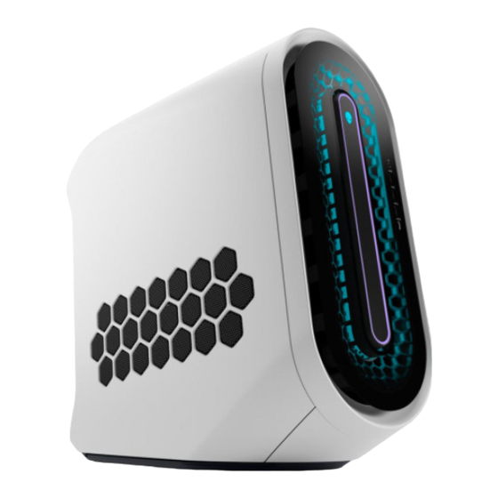
- Page 1 Alienware Aurora R15 Service Manual Regulatory Model: D30M Regulatory Type: D30M004 April 2023 Rev. A01...
- Page 2 Notes, cautions, and warnings NOTE: A NOTE indicates important information that helps you make better use of your product. CAUTION: A CAUTION indicates either potential damage to hardware or loss of data and tells you how to avoid the problem. WARNING: A WARNING indicates a potential for property damage, personal injury, or death.
-
Page 3: Table Of Contents
Contents Chapter 1: Working inside your computer....................6 Before working inside your computer..........................6 Safety instructions.................................6 Safety precautions................................7 Electrostatic discharge—ESD protection..........................7 ESD field service kit ................................8 Transporting sensitive components............................9 After working inside your computer............................9 Chapter 2: Removing and installing components..................10 Inside view of your computer.............................10 System-board components..............................12 Recommended tools................................ - Page 4 Installing the power-supply unit...........................37 Coin-cell battery................................39 Removing the coin-cell battery............................39 Installing the coin-cell battery............................. 40 Memory modules................................40 Removing the memory modules...........................40 Installing the memory modules............................41 Single-graphics card................................43 Removing the single-graphics card..........................43 Installing the single-graphics card..........................44 Graphics-card bracket and graphics-card end holder....................46 Solid-state drive.................................
- Page 5 Updating the BIOS from the F12 One Time Boot menu................... 102 Chapter 5: Troubleshooting......................... 103 SupportAssist diagnostics..............................103 System-diagnostic lights..............................103 Recovering the operating system............................ 104 Wi-Fi power cycle................................104 Drain residual flea power (perform hard reset)......................105 Chapter 6: Getting help and contacting Alienware................106...
-
Page 6: Chapter 1: Working Inside Your Computer
Working inside your computer Before working inside your computer About this task NOTE: The images in this document may differ from your computer depending on the configuration you ordered. Steps 1. Save and close all open files and exit all open applications. 2. -
Page 7: Safety Precautions
CAUTION: Exercise caution when handling rechargeable Li-ion batteries in laptops. Swollen batteries should not be used and should be replaced and disposed properly. NOTE: The color of your computer and certain components may appear differently than shown in this document. Safety precautions The safety precautions chapter details the primary steps to be taken before performing any disassembly instructions. -
Page 8: Esd Field Service Kit
● Use a wired ESD wrist strap that is properly grounded. The use of wireless anti-static straps is no longer allowed; they do not provide adequate protection. Touching the chassis before handling parts does not ensure adequate ESD protection on parts with increased sensitivity to ESD damage. -
Page 9: Transporting Sensitive Components
Transporting sensitive components When transporting ESD sensitive components such as replacement parts or parts to be returned to Dell, it is critical to place these parts in anti-static bags for safe transport. Lifting equipment Adhere to the following guidelines when lifting heavy weight equipment: CAUTION: Do not lift greater than 50 pounds. -
Page 10: Chapter 2: Removing And Installing Components
Removing and installing components NOTE: The images in this document may differ from your computer depending on the configuration you ordered. Inside view of your computer 1. Side light (optional) 2. Liquid-cooling fan assembly (optional) 3. Upper front-chassis fan 4. Memory modules 5. - Page 11 15. Power-supply unit 16. Liquid-cooling assembly (optional) 17. Rear-chassis fan (optional) NOTE: The optional components may not be present in your computer, depending on its configuration. 1. VR heat sink (2) 2. Processor fan and heat-sink assembly NOTE: The side light is not featured for the computer shown in the image.
-
Page 12: System-Board Components
System-board components 1. Front I/O-panel cable 2. SYSFAN_LED3 connector 3. Upper front-chassis connector (FAN_SYS3) 4. Coin-cell battery 5. Wireless-card slot 6. SYSFAN_LED2 connector 7. Lower front-chassis fan connector (FAN_SYS2) 8. SATA 6 Gbps drive connector (HDD1) 9. SATA 6 Gbps drive connector (HDD2) 10. -
Page 13: Recommended Tools
17. Rear-chassis fan connector (FAN SYS1) 18. Rear-chassis fan LED connector (LED FAN SYS1) 19. Liquid cooling pump fan connector (FAN PUMP) 20.Liquid-cooling pump LED connector 21. Power-supply connector (ATX3) 22. Top-chassis fan connector one (FAN_SYS4) 23. Power-supply connector (ATX2) 24.CPU socket 25.Top-chassis fan connector two (FAN_SYS5) 26.Memory-module slot, DIMM1... -
Page 14: Antenna
Table 1. Screw list (continued) Component Screw type Quantity Screw image Solid-state drive (M.2 slot one) M2x3 Solid-state drive (M.2 slot two) M2x3 Wireless card M2x3 System board #6-32x1/4" Front I/O bracket #6-32x1/4" Liquid-cooling assembly fan #6-32x1/4" Antenna Removing the antenna Prerequisites 1. -
Page 15: Installing The Antenna
Steps 1. Loosen the bolts that connect the antenna cables to the SMA connectors on the chassis. 2. Remove the antenna cables off the SMA connectors on the chassis to disconnect the external antenna from the computer. Next steps 1. Follow the procedure in After working inside your computer. -
Page 16: Installing The Cable Cover
About this task The following image indicates the location of the cable cover and provides a visual representation of the removal procedure. NOTE: The cable cover is an optional accessory. Steps Pull the cable cover from the top to lift the cable cover from the chassis. Installing the cable cover Prerequisites If you are replacing a component, remove the existing component before performing the installation procedure. -
Page 17: Left-Side Cover
Steps 1. Align the cable cover with the slots at the rear of the chassis. 2. Slide the cable cover back into its place on the rear of the chassis. Next steps 1. Follow the procedure in After working inside your computer. -
Page 18: Installing The Left-Side Cover
Steps 1. Loosen the captive screw (#6-32) that secures the side-cover release latch to the chassis. 2. Pull the side-cover release latch to release the left-side cover away from the chassis. 3. Lift the left-side panel from the chassis. Installing the left-side cover Prerequisites If you are replacing a component, remove the existing component before performing the installation procedure. -
Page 19: Top Cover
Steps 1. Locate the tabs on the left-side cover and slots on the chassis. 2. Rotate the left-side cover towards the chassis until it snaps into place. 3. Tighten the captive screw (#6-32) that secures the side-cover release latch to the chassis. Next steps 1. - Page 20 Steps 1. Press your thumbs down at the rear of the top cover, and use your fingers to pull the two rear latches out to loosen the top cover at its rear. NOTE: The top cover is secured tight to the chassis by four latches. 2.
-
Page 21: Installing The Top Cover
Installing the top cover Prerequisites If you are replacing a component, remove the existing component before performing the installation procedure. About this task The following images indicate the location of the top cover and provides a visual representation of the installation procedure. Steps Align the tabs on the top cover with the slots on the chassis and snap the top cover into place. -
Page 22: Installing The Right-Side Cover
Steps 1. Knock the top rear tab of the right-side cover until the top of right-side cover is detached from the chassis. 2. Knock the bottom rear tab of the right-side cover until the bottom of the right-side cover is detached from the chassis. 3. -
Page 23: Front Bezel
About this task Steps 1. Align the tabs on the right-side cover with the slots on the chassis. 2. Push the right-side cover towards the chassis until it snaps into place. Next steps 1. Install the cover. 2. Install the left-side cover. -
Page 24: Installing The Front Bezel
Steps 1. Place the computer in an upright position. 2. Disconnect the front I/O-panel cable from the system board. 3. Pull the tabs of the front bezel from the slots on the front panel. NOTE: Start with tab on top, proceed to the tabs on the left of the front bezel, and then to the tabs on the right of the front bezel. - Page 25 About this task The following images indicate the location of the front bezel and provide a visual representation of the installation procedure. Steps 1. Align the front bezel with the front panel. 2. Route the front I/O-panel cable through the slot on the front panel. 3.
-
Page 26: Side Light
2. Install the cover. 3. Install the left-side cover. 4. Follow the procedure in After working inside your computer. Side light Removing the side light Prerequisites 1. Follow the procedure in Before working inside your computer. 2. Remove the left-side cover. -
Page 27: Installing The Side Light
3. Remove the side-light cable from the securing clip on the chassis. 4. Remove the two screws (M3x5) that secure the side light to the chassis. 5. Lift the left side of the side-light bar slightly from the screw hole at the rear of the chassis. 6. -
Page 28: 2.5-Inch Hard Drive
Next steps 1. Install the front bezel. 2. Install the right-side cover. 3. Install the cover. 4. Install the left-side cover. 5. Follow the procedure in After working inside your computer. 2.5-inch hard drive Removing the 2.5-inch hard drive Prerequisites 1. -
Page 29: Installing The 2.5-Inch Hard Drive
Steps 1. Disconnect the data and power cables from the hard drive. 2. Press the release tabs on the hard-drive carrier and slide the hard-drive carrier out of the hard-drive cage. 3. Pry the hard-drive carrier to release the tabs on the carrier from the slots on the hard drive. 4. - Page 30 NOTE: Note the orientation on the hard-drive carrier to replace it correctly. Steps 1. Align the hard drive with the pins on the hard-drive carrier. 2. Using the tabs on the opposite side, flex open the carrier to insert the pins on the other side. 3.
-
Page 31: 3.5-Inch Hard Drive
Next steps 1. Install the left-side cover. 2. Follow the procedure in After working inside your computer. 3. Verify if the storage device is installed correctly (optional): a. If you are replacing a storage device which does not have the operating system installed, follow the steps in Identifying storage device in device manager. - Page 32 Steps 1. Disconnect the data and power cables from the hard drive. 2. Press the release tabs on the hard-drive carrier and slide the hard-drive carrier out of the hard-drive cage. 3. Pry the hard-drive carrier to release the tabs on the carrier from the slots on the hard drive. 4.
-
Page 33: Installing The 3.5-Inch Hard Drive
NOTE: Note the orientation of the hard drive so that you can replace it correctly. Installing the 3.5-inch hard drive Prerequisites If you are replacing a component, remove the existing component before performing the installation procedure. About this task The following images indicate the location of the 3.5-inch hard drive and provide a visual representation of the installation procedure. -
Page 35: Identifying The Storage Device In Device Manager
NOTE: Note the orientation on the hard-drive carrier to replace it correctly. Steps 1. Align the hard drive with the pins on the hard-drive carrier. 2. Using the tabs on the opposite side, flex open the carrier to insert the pins on the other side. 3. -
Page 37: Installing The Power-Supply Unit
Steps 1. Disconnect the power-supply unit cables from the power-supply unit extension cables on the right side of the computer. 2. Note the cable routing when removing the power-supply unit cables through the slot on the right side of the computer. 3. - Page 38 Steps 1. Lay the computer on the right side. 2. Slide and place the power-supply unit on the chassis. 3. Align the screw holes on the power-supply unit with the screw holes on the chassis. 4. Replace the four screws (#6-32x1/4") that secure the power-supply unit to the chassis. 5.
-
Page 39: Coin-Cell Battery
6. Replace the two screws (#6-32x1/4") that secure the power-supply unit bracket to the power-supply unit. 7. Replace the graphics-card bracket and slide the release latch to the lock position. 8. Route the power-supply unit cables through the securing clip. 9. -
Page 40: Installing The Coin-Cell Battery
Steps 1. Lay the computer on the right side. 2. Press the battery-release lever away from the coin-cell battery until the coin-cell battery pops up. 3. Lift the coin-cell battery out of its socket. Installing the coin-cell battery Prerequisites If you are replacing a component, remove the existing component before performing the installation procedure. About this task The following images indicate the location of the coin-cell battery and provide a visual representation of the installation procedure. -
Page 41: Installing The Memory Modules
About this task The following images indicate the location of the memory modules and provide a visual representation of the removal procedure. Steps 1. Lay the computer on the right side. 2. Push the securing clips away from the memory module. 3. - Page 42 Steps 1. Ensure that the securing clips are extended away from the memory-module slot. 2. Align the notch on the memory module with the tab on the memory-module slot. 3. Insert the memory module into the memory-module slot and press the memory module down until it snaps into position and the securing clips lock in place.
-
Page 43: Single-Graphics Card
Single-graphics card Removing the single-graphics card Prerequisites 1. Follow the procedure in Before working inside your computer. 2. Remove the left-side cover. About this task The following images indicate the location of the single-graphics card and provide a visual representation of the removal procedure. -
Page 44: Installing The Single-Graphics Card
Steps 1. Lay the computer on the right side. 2. Slide the release latch to its unlock position and lift the graphics-card end holder away from the PCIe fan. NOTE: Skip this step if your graphics card does not ship with a graphics-card end holder. 3. - Page 45 Steps 1. Place the card into the PCIe slot and press down firmly until the single-graphics card snaps into place. 2. Close the expansion-card door and snap the latch back into position. 3. Replace the graphics-card end holder over the PCIe fan and slide the latch into its lock position. NOTE: Skip this step if your graphics card does not ship with a graphics-card end holder.
-
Page 46: Graphics-Card Bracket And Graphics-Card End Holder
After working inside your computer. Graphics-card bracket and graphics-card end holder The following table shows whether the graphics-card bracket or/and the graphics-card end holder is/are shipped with your Alienware Aurora R15. Table 3. Graphics-card bracket and graphics-card end holder Graphics card Graphics-card bracket... -
Page 47: Installing The 2230 Solid-State Drive In Ssd Slot One
Steps 1. Remove the screw (M2x3) that secures the 2230 solid-state drive to the system board. 2. Slide and lift the 2230 solid-state drive off solid-state drive slot one on the system board. Installing the 2230 solid-state drive in SSD slot one Prerequisites If you are replacing a component, remove the existing component before performing the installation procedure. -
Page 48: Removing The 2280 Solid-State Drive In Ssd Slot One
Steps 1. Align the notch on the 2230 solid-state drive with the tab on the SSD slot one on the system board. 2. Insert the 2230 solid-state drive at a 45-degree angle into the system board. 3. Press the other end of the 2230 solid-state drive down and replace the screw (M2x3) that secures the 2230 solid-state drive to the system board. -
Page 49: Installing The 2280 Solid-State Drive In Ssd Slot One
Steps 1. Remove the screw (M2x3) that secures the 2280 solid-state drive to the system board. 2. Slide and lift the 2280 solid-state drive off SSD slot one on the system board. Installing the 2280 solid-state drive in SSD slot one Prerequisites If you are replacing a component, remove the existing component before performing the installation procedure. -
Page 50: Removing The 2230 Solid-State Drive In Ssd Slot Two
Steps 1. Align the notch on the 2280 solid-state drive with the tab on the SSD slot one on the system board. 2. Insert the 2280 solid-state drive at a 45-degree angle into the system board. 3. Press the other end of the 2280 solid-state drive down and replace the screw (M2x3) that secures the 2280 solid-state drive to the system board. -
Page 51: Installing The 2230 Solid-State Drive In Ssd Slot Two
Steps 1. Remove the screw (M2x3) that secures the 2230 solid-state drive to the system board. 2. Slide and lift the 2230 solid-state drive off SSD slot two on the system board. Installing the 2230 solid-state drive in SSD slot two Prerequisites If you are replacing a component, remove the existing component before performing the installation procedure. -
Page 52: Removing The 2280 Solid-State Drive In Ssd Slot Two
Steps 1. Align the notch on the 2230 solid-state drive with the tab on the SSD slot two on the system board. 2. Insert the 2230 solid-state drive at a 45-degree angle into the system board. 3. Press the other end of the 2230 solid-state drive down and replace the screw (M2x3) that secures the 2230 solid-state drive to the system board. -
Page 53: Installing The 2280 Solid-State Drive In Ssd Slot Two
Steps 1. Remove the screw (M2x3) that secures the 2280 solid-state drive to the system board. 2. Slide and lift the 2280 solid-state drive off SSD slot two on the system board. Installing the 2280 solid-state drive in SSD slot two Prerequisites If you are replacing a component, remove the existing component before performing the installation procedure. -
Page 54: Processor Fan And Heat-Sink Assembly
Steps 1. Align the notch on the 2280 solid-state drive with the tab on the SSD slot two on the system board. 2. Insert the 2280 solid-state drive at a 45-degree angle into the system board. 3. Press the other end of the 2280 solid-state drive down and replace the screw (M2x3) that secures the 2280 solid-state drive to the system board. -
Page 55: Installing The Processor Fan And Heat-Sink Assembly
About this task The following images indicate the location of the processor fan and heat-sink assembly and provide a visual representation of the removal procedure. Steps 1. Lay the computer on the right side. 2. Disconnect the processor-fan cable from the system board. 3. -
Page 56: Processor Liquid-Cooling Assembly
Steps 1. Place the processor fan and heat-sink assembly on the processor. 2. Align the captive screws on the processor fan heat-sink assembly with the screw holes on the system board. 3. In sequential order, tighten the four captive screws that secure the processor fan and heat-sink assembly to the system board. 4. - Page 57 About this task The following images indicate the location of the processor liquid-cooling assembly and provide a visual representation of the removal procedure. Steps 1. Lay the computer on the right side. 2. Lift the side light bar. 3. Remove the two screws (M3x5) that secures the radiator and fan assembly to the chassis. 4.
-
Page 58: Installing The Processor Liquid-Cooling Assembly
7. Release the spring latch and lift the processor-cooling assembly, along with the cables, off the system board. Installing the processor liquid-cooling assembly Prerequisites If you are replacing a component, remove the existing component before performing the installation procedure. CAUTION: Incorrect alignment of the processor liquid-cooling assembly can damage the system board and processor. CAUTION: If either the processor or the heat sink is replaced, use the thermal grease that is provided in the kit to ensure that thermal conductivity is achieved. - Page 59 Steps 1. Align the screw hole of the radiator and fan assembly to the screw hole on the chassis and make sure that the spring latch is locked. NOTE: Ensure that the hoses are facing the front of the computer. 2.
-
Page 60: Liquid-Cooling Assembly Fan
7. Push the side light bar down. Next steps 1. Install the left-side cover. 2. Follow the procedure in After working inside your computer. Liquid-cooling assembly fan Removing the liquid-cooling assembly fan Prerequisites 1. Follow the procedure in Before working inside your computer. -
Page 61: Installing The Liquid-Cooling Assembly Fan
Steps 1. Remove the four screws (#6-32x1/4") that secures the left liquid-cooling assembly fan to the liquid-cooling assembly. 2. Lift the left liquid-cooling assembly fan off the liquid-cooling assembly. 3. Remove the four screws (#6-32x1/4") that secures the right liquid-cooling assembly fan to the liquid-cooling assembly. 4. -
Page 62: Processor
Steps 1. Align and place the left liquid-cooling assembly fan on the liquid-cooling assembly. 2. Replace the four screws (#6-32x1/4") that secures the left liquid-cooling assembly fan to the liquid-cooling assembly. 3. Align and place the right liquid-cooling assembly fan off the liquid-cooling assembly. 4. -
Page 63: Installing The Processor
About this task The following images indicate the location of the processor and provide a visual representation of the removal procedure. Steps 1. Press the release lever down and then push it away from the processor to release it from the tab. 2. - Page 64 Steps 1. Ensure that the release lever on the processor socket is fully extended and the processor cover is fully open. CAUTION: Position the processor correctly in the processor socket to avoid permanent damage to the processor. 2. Align the pin-1 corner on the processor with the pin-1 corner on the processor socket, and then place the processor in the processor socket.
-
Page 65: Wireless Card
Wireless card Removing the wireless card Prerequisites 1. Follow the procedure in Before working inside your computer. 2. Remove the left-side cover. About this task The following images indicate the location of the wireless card and provide a visual representation of the removal procedure. Steps 1. - Page 66 About this task The following images indicate the location of the wireless card and provide a visual representation of the installation procedure. Steps 1. Connect the antenna cables to the wireless card. The following table provides the antenna-cable color scheme for the wireless card supported by your computer. Table 4.
-
Page 67: Sma Cable
SMA cable Removing the SMA cable Prerequisites 1. Follow the procedure in Before working inside your computer. 2. Remove the left-side cover. 3. Remove the single-graphics card. 4. Remove the wireless card. About this task The following images indicate the location of an SMA cable and provide a visual representation of the removal procedure. -
Page 68: Installing The Sma Cable
Steps 1. Remove the washer and nuts that secure the SMA cable connector to the chassis. 2. Route the SMA cable assembly through the slot on the rear I/O. 3. Remove the SMA cable from the securing clip on the system board. 4. -
Page 70: Rear-Chassis Fan
Steps 1. Align and place the SMA cable connector on the chassis. 2. Route the SMA cable under the PCIe x16 slot. 3. Insert the SMA cable to the securing clip on the system board. 4. Route the SMA cable assembly through the slot on the rear I/O. 5. -
Page 71: Installing The Rear-Chassis Fan
Steps 1. Lay the computer on its right side. 2. Disconnect the rear-chassis fan cable from the system board. 3. Remove the screw (M3x5) that secures the rear-chassis fan to the chassis. 4. Slide and lift the rear-chassis off the chassis. Installing the rear-chassis fan Prerequisites If you are replacing a component, remove the existing component before performing the installation procedure. -
Page 72: Lower Front-Chassis Fan
Steps 1. Lay the computer on its right side. 2. Align the rear-chassis fan with the slot on the chassis. 3. Replace the screw (M3x5) that secures the rear-chassis fan to the chassis. 4. Connect the rear-chassis fan cable to the system board. Next steps 1. -
Page 73: Installing The Lower Front-Chassis Fan
2. Remove the left-side cover. About this task The following images indicate the location of the lower front-chassis fan and provide a visual representation of the removal procedure. Steps 1. Lay the computer on its right side. 2. Disconnect the lower front-chassis fan cable from the system board. 3. - Page 74 About this task The following images indicate the location of the lower front-chassis fan and provide a visual representation of the installation procedure. Steps 1. Lay the computer on its right side. 2. Align the tabs on the lower front-chassis fan with the slots on the chassis. 3.
-
Page 75: Upper Front-Chassis Fan
Upper front-chassis fan Removing the upper front-chassis fan Prerequisites 1. Follow the procedure in Before working inside your computer. 2. Remove the left-side cover. About this task The following images indicate the location of the upper front-chassis fan and provide a visual representation of the removal procedure. -
Page 76: Installing The Upper Front-Chassis Fan
Installing the upper front-chassis fan Prerequisites If you are replacing a component, remove the existing component before performing the installation procedure. About this task The following images indicate the location of the upper front-chassis fan and provide a visual representation of the installation procedure. -
Page 77: Top-Chassis Fan
Top-chassis fan Removing the top-chassis fan Prerequisites 1. Follow the procedure in Before working inside your computer. 2. Remove the left-side cover. About this task The following images indicate the location of the top-chassis fan and provide a visual representation of the removal procedure. Steps 1. -
Page 78: Vr Heat Sink
Steps 1. Lay the computer on the right side. 2. Align and place the top-chassis fan on the chassis. 3. Connect the top-chassis fan cables from the system board. 4. Replace the two screws (M3x5) that secures the top-chassis fan to the chassis. VR heat sink Removing the VR heat sink Prerequisites... - Page 79 Steps 1. Lay the computer on the right side. 2. Loosen the captive screws that secure the VR heat sink to the system board.
-
Page 80: Installing The Vr Heat Sink
3. Repeat the same process for the other VR heat sink. 4. Lift the VR heat sink (2) off the system board. Installing the VR heat sink Prerequisites If you are replacing a component, remove the existing component before performing the installation procedure. NOTE: Before installing the new VR heatsink, ensure to remove the protective foil from the thermal pad. -
Page 81: System Board
Steps 1. Align the captive screws of the VR heat sink with the screw holes on the system board. 2. Tighten the two captive screws that secure the VR heat sink to the system board. 3. Repeat the same procedure for the other VR heat sink. Next steps 1. - Page 82 2. Remove the left-side cover. 3. Remove the cover. 4. Remove the right-side cover. 5. Remove the front bezel. 6. Remove the memory modules. 7. Remove the single-graphics card. 8. Remove the 2230 solid-state drive or the 2280 solid-state drive in SSD slot one, as applicable.
- Page 83 1. Front I/O-panel cable 2. SYSFAN_LED3 connector 3. Upper front-chassis connector (FAN_SYS3) 4. Coin-cell battery 5. Wireless-card slot 6. SYSFAN_LED2 connector 7. Lower front-chassis fan connector (FAN_SYS2) 8. SATA 6 Gbps drive connector (HDD1) 9. SATA 6 Gbps drive connector (HDD2) 10.
- Page 84 21. Power-supply connector (ATX3) 22. Top-chassis fan connector one (FAN_SYS4) 23. Power-supply connector (ATX2) 24.CPU socket 25.Top-chassis fan connector two (FAN_SYS5) 26.Memory-module slot, DIMM1 27. Memory-module slot, DIMM2 28. SATA power connector (SATA PWR) 29.Side-light connector (SIDE LIGHT) The following images indicate the location of the system board and provide a visual representation of the removal procedure.
- Page 85 Steps 1. Disconnect the hard-drive data cables from the system board. 2. Disconnect the processor-power cables from the system board. 3. Disconnect the system-board power cables from the system board. 4. Disconnect the top-chassis fan power cable from the system board. 5.
-
Page 86: Installing The System Board
Installing the system board Prerequisites If you are replacing a component, remove the existing component before performing the installation procedure. About this task The following image indicates the connectors on your system board. 1. Front I/O-panel cable 2. SYSFAN_LED3 connector 3. - Page 87 5. Wireless-card slot 6. SYSFAN_LED2 connector 7. Lower front-chassis fan connector (FAN_SYS2) 8. SATA 6 Gbps drive connector (HDD1) 9. SATA 6 Gbps drive connector (HDD2) 10. Power-supply connector (ATX1) 11. Solid-state drive slot (M.2 PCIe SSD-1) 12. Solid-state drive slot (M.2 PCIe SSD-0) 13.
- Page 89 Steps 1. Slide the front I/O-ports on the system board into the front I/O-slot on the chassis and align the screw holes on the system board with the standoffs on the chassis. 2. Place the system board on the standoffs on the chassis. 3.
- Page 90 4. Install the wireless card. 5. Install the 2230 solid-state drive or the 2280 solid-state drive in SSD slot one, as applicable. 6. Install the 2230 solid-state drive or the 2280 solid-state drive in SSD slot two, as applicable. 7. Install the single-graphics card.
-
Page 91: Chapter 3: Drivers And Downloads
Drivers and downloads When troubleshooting, downloading or installing drivers it is recommended that you read the Dell Knowledge Base article, Drivers and Downloads FAQ 000123347. -
Page 92: Chapter 4: System Setup
System setup CAUTION: Unless you are an expert computer user, do not change the settings in the BIOS Setup program. Certain changes can make your computer work incorrectly. NOTE: Depending on the computer and its installed devices, the items listed in this section may or may not be displayed. NOTE: Before you change BIOS Setup program, it is recommended that you write down the BIOS Setup program screen information for future reference. -
Page 93: System Setup Options
Displays the current date in mm/dd/yy format. BIOS Version Displays the BIOS version number. Product Name Displays the product name. Default: Alienware Aurora R15 Service Tag Displays the service tag of your computer. Asset Tag Displays the asset tag of your computer. - Page 94 Table 7. System setup options—Advanced menu (continued) Advanced Multiple-Core Support Allows you to configure Multiple-Core support. Default: All Multiple Atom cores Multiple Atom cores Allows you to configure Multiple Atom cores. Default: All Trusted Execution Trusted Execution Allows you to enable or disable Trusted Execution. Default: Enabled Integrated NIC Integrated NIC...
- Page 95 Table 7. System setup options—Advanced menu (continued) Advanced Default: Enabled USB PowerShare in S4/S5 state Allows you to charge external devices. Default: Disabled USB PowerShare in Sleep State Allows you to enable front the USB devices to wake the system from sleep state.
- Page 96 Table 7. System setup options—Advanced menu (continued) Advanced BIOS Recovery from Hard Drive Enables the computer to recover from certain corrupted BIOS conditions from a recovery file on the user primary hard drive or an external USB key. NOTE: BIOS Recovery from Hard Drive is not available for Self-encrypting drives (SED).
- Page 97 Table 8. System setup options—Security menu (continued) Security Password Change Allows you to enable or disable password change on the computer. Default: Permitted Absolute Enable or disable the BIOS module interface of the optional Absolute Persistence Module service from Absolute Software.
-
Page 98: System And Setup Password
Table 8. System setup options—Security menu (continued) Security Reset all Keys Delete all Keys Table 9. System setup options—Boot menu Boot Boot List Option Displays the available boot devices. Default: UEFI File Browser Add Boot Option Allows you to set the boot path in the boot option list. File Browser Del Boot Option Allows you to delete the boot path in the boot option list. -
Page 99: Assigning A System Setup Password
Assigning a system setup password Prerequisites You can assign a new System or Admin Password only when the status is in Not Set. About this task To enter the system setup, press F12 immediately after a power-on or reboot. Steps 1. -
Page 100: Clearing Bios (System Setup) And System Passwords
The following images indicate the location of the CMOS jumper on the system board and provide a visual representation of the clearing CMOS procedure. Steps 1. Turn off the computer and disconnect the power cable from the computer. 2. Remove the left-side cover. -
Page 101: Updating The Bios
Steps 1. Turn off the computer and disconnect the power cable from the computer. 2. Remove the left-side cover. 3. Lay the computer on its right side. 4. Locate the 2-pin password reset jumper on the system board. 5. Ensure that the jumper is on the pair of password pins (JM34) and remove the jumper. 6. -
Page 102: Updating The Bios Using The Usb Drive In Windows
For more information about how to update the system BIOS, search in the Knowledge Base Resource at www.dell.com/support. Updating the BIOS using the USB drive in Windows Steps 1. Follow the procedure from step 1 to step 6 in Updating the BIOS in Windows to download the latest BIOS setup program file. -
Page 103: Chapter 5: Troubleshooting
Troubleshooting SupportAssist diagnostics About this task The SupportAssist diagnostics (previously known as ePSA diagnostics) performs a complete check of your hardware. The SupportAssist diagnostics is embedded in the BIOS and is launched by it internally. The SupportAssist diagnostics provides a set of options for particular devices or device groups. -
Page 104: Recovering The Operating System
Table 12. Diagnostic light codes (continued) Diagnostic light codes Problem description (Amber, White) No memory or Random-Access Memory (RAM) detected Memory or Random-Access Memory (RAM) failure Invalid memory installed System board/Chipset Error CMOS battery failure PCI of Video card/chip failure BIOS Recovery 1: BIOS recovery image not found BIOS Recovery 2: Recovery image found but invalid... -
Page 105: Drain Residual Flea Power (Perform Hard Reset)
Drain residual flea power (perform hard reset) About this task Flea power is the residual static electricity that remains in the computer even after it has been powered off and the battery is removed. For your safety, and to protect the sensitive electronic components in your computer, you are requested to drain residual flea power before removing or replacing any components in your computer. -
Page 106: Chapter 6: Getting Help And Contacting Alienware
Getting help and contacting Alienware Self-help resources You can get information and help on Alienware products and services using these online self-help resources: Table 13. Alienware products and online self-help resources Self-help resources Resource location Information about Alienware products and services www.alienware.com...
Need help?
Do you have a question about the Aurora R15 and is the answer not in the manual?
Questions and answers