Advertisement
Quick Links
Advertisement

Subscribe to Our Youtube Channel
Related Manuals for Outback Rebel

Summary of Contents for Outback Rebel
- Page 1 Quick Start Guide www.outbackguidance.com...
- Page 2 PN 875-0412-01 Rev E1...
- Page 3 The following sections provide instructions on using terminal onscreen Help and list support contact information. Schedule an appointment with your dealer to complete the installation of your Visit our support page at: outbackguidance.zendesk.com, to find a PDF Rebel User Guide and other support vehicle's REBEL autosteer kit.
-
Page 4: Kit Contents
Skip to close the Start Up Menu then refer to REBEL Help on your terminal-see "Using Onscreen Help" on page 28. REBEL must have a GPS position to begin a job and provide guidance. REBEL starts acquiring a DGPS NOTE:... - Page 5 POWER UP AND REGISTRATION KIT CONTENTS 3. Upon power up, REBEL completes a self-test Part Number Description Photograph and the screen at right appears. 4. Acknowledge the warning and accept the End 050-0041-01 COM2 cable User License Agreement (EULA): Connects COM2 port on terminal to foot a.
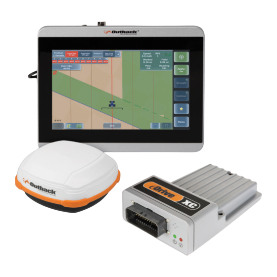
- Page 6 Unpack your REBEL Row-Crop kit and identify the parts as shown. Depending on the components of your system you may have to power up more than one component. For example, if your REBEL system includes eDriveXC you must power up both the REBEL terminal and the eDriveXC ECU. Part Number...
-
Page 7: Connections And Installation
KIT CONTENTS Connecting the Cables to the Terminal Part Number Description Photograph Using "REBEL Terminal Overview" on page 13, "REBEL Connection Diagrams" starting on 050-0041-01 COM2 cable page 14, and the photo at right as guides, Connects COM2 port on terminal to foot... - Page 8 Connecting to a Power Source 050-0020-01 LAN/USB cable Using "REBEL Terminal Overview" on page 13 and "REBEL Connection Diagrams" starting on page 14 as guides, connect the power adapter cable to your preferred power source. Connects LAN/USB port on terminal to eDriveXC cable 1.
- Page 9 CONNECTIONS AND INSTALLATION KIT CONTENTS 3. Attach the shorter leads of the Part Number Description Photograph power cable to the power posts on the IBBC bracket. Replace 050-0041-01 COM2 cable the washers and nuts then tighten. Connects COM2 port on terminal to foot switch 050-0045-01 Antenna extension cable...
-
Page 10: Optional Upgrades
OPTIONAL UPGRADES CONNECTIONS AND INSTALLATION a. Insert the 2-pin weather Optional Upgrades pack closest to the negative ring terminal into 10” Terminal Kit Contents (optional) the relay next to the power posts on the IBBC bracket. Unpack your 10" terminal kit and identify the parts as shown. Apply enough pressure to snap the plug into the relay. - Page 11 CONNECTIONS AND INSTALLATION OPTIONAL UPGRADES Switchbox Kit Contents (optional) Connecting to Your ISOBUS ECU Unpack your switchbox kit and identify the part as shown. See "Installing the Switchbox" on page 1 for instructions If your vehicle is ISOBUS-ready see "ISOBUS-Ready Vehicle Connections" immediately following. If your vehicle is on installing the switchbox in your preferred location.
- Page 12 OPTIONAL UPGRADES CONNECTIONS AND INSTALLATION Installing the Lightbar RTK Rover Kit Contents (optional) The lightbar kit includes suction cup mounting hardware (with mounting ball), a separate mounting ball, and an Unpack your RTK rover kit and identify the parts as shown. See "Installing the Rover Radio" on page 18 for extension cable.
- Page 13 Unpack your ISOBUS cable kit and identify the parts as shown. See "Connecting to Your ISOBUS ECU" on page 20 for instructions on connecting this cable. A camera is not included in your REBEL kit; you must purchase that separately (not sold by Outback Guidance). Follow the camera manufacturer's instructions for installing your cameras.
- Page 14 You should install the antenna on the vehicle's left/right centerline and front/back pivot point. If you cannot install the antenna at the exact centerline and/or pivot point, refer to REBEL Help installed on your terminal for instructions on entering offsets for these values.
- Page 15 CONNECTIONS AND INSTALLATION CONNECTIONS AND INSTALLATION REBEL Terminal Overview Connection Diagram #3 - ISOBUS Retrofit Kit The following table shows the front and rear views of the REBEL terminal and describes each numbered feature. Item Description Views Touchscreen USB port...
- Page 16 CONNECTIONS AND INSTALLATION CONNECTIONS AND INSTALLATION REBEL Connection Diagrams Connection Diagram #2 - With ISOBUS Connection Diagram #1 - Without ISOBUS OUTBACKGUIDANCE.COM OUTBACKGUIDANCE.COM...
Need help?
Do you have a question about the Rebel and is the answer not in the manual?
Questions and answers