Table of Contents
Advertisement
Style Selections® is a registered trademark
of LF, LLC. All Rights Reserved.
Purchase Date
Questions, problems, missing parts? Before returning to your retailer, call our customer
service department at 1-877-888-8225, 8 a.m. - 6 p.m., EST, Monday - Thursday, 8 a.m. -
5 p.m., EST, Friday.
PH18962
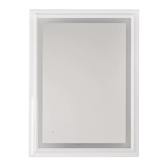
LIGHTED MIRROR
1
ITEM
#1210978
MODEL #MIR7191
Français p. 12
Español p. 23
ATTACH YOUR RECEIPT HERE
800413
Advertisement
Table of Contents

Related Manuals for Style selections MIR7191


Summary of Contents for Style selections MIR7191
- Page 1 ITEM #1210978 LIGHTED MIRROR MODEL #MIR7191 Style Selections® is a registered trademark of LF, LLC. All Rights Reserved. Français p. 12 Español p. 23 ATTACH YOUR RECEIPT HERE 800413 Purchase Date Questions, problems, missing parts? Before returning to your retailer, call our customer service department at 1-877-888-8225, 8 a.m.
-
Page 2: Table Of Contents
TABLE OF CONTENTS Package Contents .......................2 Hardware Contents ......................... Safety Information ....................... Preparation ......................... Initial Installation ......................... Plug-In Installation ......................Hardwire Installation ......................Operating Instructions ......................Care and Maintenance .......................11 Troubleshooting........................Warranty ..........................PACKAGE CONTENTS PART DESCRIPTION QUANTITY Fixture Touch Sensor (Preassembled to Fixture (A)) Power Cord (Preassembled to Fixture (A)) -
Page 3: Hardware Contents
HARDWARE CONTENTS (shown actual size) Machine Fixture Plastic Wire Screw Screw Anchor Connector Qty. 2 Qty. 4 Qty. 4 Qty. 3 SAFETY INFORMATION READ AND SAVE THESE INSTRUCTIONS. For installation options not covered in this manual, consult a qualified electrician. DANGER •... - Page 4 SAFETY INFORMATION • To reduce the risk of fire, electrical shock or personal injury, wire connectors provided with this light fixture are designed to accept only one 12-gauge house wire and two lead wires from the light fixture. If your house wire is larger than 12-gauge or there is more than one house wire to connect to the corresponding fixture lead wires, consult an electrician for the proper size wire connectors to use.
-
Page 5: Preparation
SAFETY INFORMATION CAUTION • TURN OFF ELECTRICITY at main fuse box (or circuit breaker box) before beginning installation by removing the fuse (or switching the circuit breaker off). • If you are not sure the lighting system has a grounding means, DO NOT attempt to install this fixture. Contact a qualified, licensed electrician for information regarding the proper grounding methods as required by the local electrical code in your area. -
Page 6: Plug-In Installation
INITIAL INSTALLATION Determine the approximate location for the fixture (A). Template Place a template (not included) against the wall, and mark the location of the holes using a pencil or a marker (not included). If mounting surface is wood, use a 5/64 in. drill bit (not included) to drill the fixture screws (AA) in wood at marked locations. -
Page 7: Hardwire Installation
PLUG-IN INSTALLATION Hang fixture (A) using the keyhole slots on the back of fixture (A). Keyhole Slot Insert the power cord (C) preassembled on fixture (A) into proper wall outlet. WARNING: The power cord is equipped with a three-prong grounded plug that must be inserted into a matching receptacle. - Page 8 HARDWIRE INSTALLTION Remove the preassembled wire connectors to Wire discharge the power cord (C). Connectors Inside the wire box, remove ONLY the plastic piece from the power cord (C), so the power Wire Box cord (C) can be removed from the fixture (A). Pull power cord (C) from the bottom of the wire box.
- Page 9 HARDWIRE INSTALLTION Prepare wires by stripping 3/4 in. of insulation from wire ends using wire strippers (not included). Connect WHITE wire from fixture (A) to WHITE wire Wire box from outlet box using existing wire connector or wire cover connector (CC). Connect BLACK wire from fixture (A) to BLACK wire WHITE WHITE...
- Page 10 HARDWIRE INSTALLTION Attach the wire box cover to outlet box (not included) using outlet box screws or the Wire box machine screws (DD). NOTE: If the outlet cover box screws required for your outlet box are of a different size than the machine screws (DD), consult a licensed electrician before proceeding.
-
Page 11: Operating Instructions
OPERATING INSTRUCTIONS 1. Tapping the touch sensor (B) on fixture (A) turns light ON and OFF. 2. Pressing the touch sensor (B) for 3 seconds dims the light. CARE AND MAINTENANCE • Wipe fixture with soft, damp cloth. Do not use an abrasive cleaner on fixture. TROUBLESHOOTING WARNING: Before beginning work, shut off the power supply to avoid electrical shock.
Need help?
Do you have a question about the MIR7191 and is the answer not in the manual?
Questions and answers