
Subscribe to Our Youtube Channel
Related Manuals for GEZE E260 Series


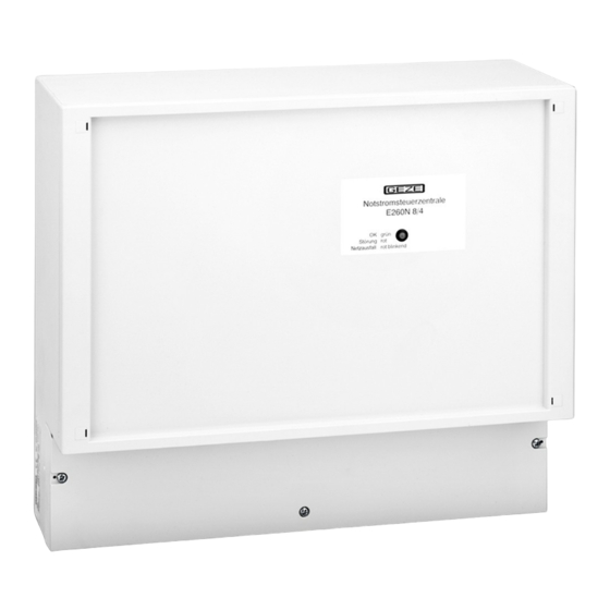
Summary of Contents for GEZE E260 Series
- Page 1 RWA Emergency Power Supply System E260 N2/N4/N8/N12 Connection Schema 118533-4 Connection Schema Emergency Power Supply System E260 N2/1 to N12/2-24V DC...
-
Page 2: Table Of Contents
Contents 1. Short description ................................2 2. Layout plan ..................................3 3.1 Mains connection ................................4 3.2 Connection of the battery ............................4 3.3 Connection of smoke and heat difference sensor ...................4 3.4 Operation without smoke or heat difference senosr ..................4 3.5 Connection of SHE switch FT4/24V DC - VdS ....................5 3.6 Connection of fire alarm system (BMS) / remote trip release ..............5... -
Page 3: Short Description
Routing of cables and connection to the mains voltage must be carried out by a qualified electrician GEZE does not uphold any warranty if the product is used in combination with products by third parties For all types of installations the relevant regulations must be observed, in particular VDE 0833/0815. -
Page 4: Layout Plan
2. Layout plan SHE switches of type FT4-24V Malfunct. DC-VdS must be used only! Oper. OK Win. OPEN LED - fire +24V Alarm switch CLOSE switch Resistors: leave in the last switch! Resistor 15k, 5% (for N12: 3K9, 1%) Smoke detector RM 1003/24V or heat diff. -
Page 5: Mains Connection
3.1 Mains connection Information on the mains connection: Terminal block E260N mains voltage 230V AC, 50Hz, back-up fuse10A, connecting line 3x1,5mm² or 3x2,5mm² with GN/YE connect protection earth to PE-terminal to switch off the system the building installation must Mains 230V AC include an isolating device (switch, disengageable safety cutout that can be turned off). -
Page 6: Connection Of She Switch Ft4/24V Dc - Vds
3.5 Connection of SHE switch FT4/24V DC - VdS last SHE switch Both resistors: leave in the last switch OPEN CLOSE +24V Alarm switch LED-fire Win. OPEN Oper. OK Malfunction 2. SHE-switch Both resistors: remove in all preceding switches! OPEN switch CLOSE +24V... -
Page 7: Connection Of Motors
4.1 Connection of motors 4.1.1 Linear, 1 cable section Monitoring of the motor supply line: using conductor no. 3 in each group. Insulate conductor no. 3 of all other motors of the group Last motor motor motor Insulate Insulate conduct. 3 conduct. -
Page 8: Connections Of Motors Without Integrated Line Monitoring
4.1.3 Connections of motors without integrated line monitoring Last motor motor motor Motor Motor Motor 24V DC 24V DC 24V DC Terminal block E260N Conduit box Install 1 resistor 2k2Ώ and 2 diodes e.g. 1N4007 Motor for line monitoring group in last conduit box. -
Page 9: Connection Of Ventilator Switch
5.1 Connection of ventilator switch Terminal block E260N Ventilat. switch 2 3 4 5 6 7 LTA-24 1 3 4 4 2 CL OPEN green red Terminal block E260N Ventil. switch 2 3 4 5 6 7 LTA-230 1 3 4 4 2 Terminal block E260N Terminal block E260N Ventil. -
Page 10: Connection Of Several Ventilator Switches Per Ventilator Group
5.2 Connection of several ventilator switches per ventilator group 5.2.1 Ventilator switch LTA-230 Terminal block E260N Ventilat. switch 2 3 4 5 6 7 LTA-230 last switch 1 switch 1 3 4 4 2 1 3 4 4 2 1 3 4 4 2 For LTA-24 the terminals 5, 6 and 7 are always connected in parallel. -
Page 11: Connection Of Timer
6 Connection of timer 6.1 Timer per ventilator group Terminal block E260N Ventil. switch The timer settings must be 2 3 4 5 6 7 programmed as pulse signals. The ventilator switch will not function properly with sustained signal. e.g. LTA-230 1 3 4 4 2 1 2 3... -
Page 12: Connection Of Rain/Wind Control Unit
7.1 Connection of rain/wind control unit Terminal block Set mode of operation Evaluation unit for “relay in common“ rain/wind control unit using jumper. Rain Weather LEDs Wind Mains station N PE Mains Connect weather station, etc. in acc. 230V AC Terminal block with connection scheme 45600-9-9520 E260N... -
Page 13: Potential-Free Signaling Contacts (Optional)
8.3 Connection of a sounder with internal supply voltage (max.30mA) Relay Relay Relay Mains 230V AC Ventil. switch Alarm Wind. OPEN Malfunction 4 5 6 7 e.g. GEZE +24V, max. 30mA Sounder 24V DC Id. no. 072112 118533-4 Connection Schema Emergency Power Supply System E260 N2/1 to N12/2-24V DC... - Page 14 118533-4 Connection Schema Emergency Power Supply System E260 N2/1 to N12/2-24V DC...
- Page 15 118533-4 Connection Schema Emergency Power Supply System E260 N2/1 to N12/2-24V DC...
- Page 16 97944 Boxberg-Schweigern Tel. +49 (0) 7930 9294 0 Baltic States Iberia Singapore Fax +49 (0) 7930 9294 10 GEZE GmbH Baltic States office GEZE Iberia S.R.L. GEZE (Asia Pacific) Pte, Ltd. E-Mail: sk.de@geze.com E-Mail: office-latvia@geze.com E-Mail: info@geze.es E-Mail: gezesea@geze.com.sg www.geze.com...
Need help?
Do you have a question about the E260 Series and is the answer not in the manual?
Questions and answers