Table of Contents
Advertisement
Quick Links
Pioneering for You
Wilo-Control MS-L 2x4kW
de Einbau- und Betriebsanleitung
en Installation and operating instructions
fr
Notice de montage et de mise en service
es
Instrucciones de instalación y funcionamiento
it
Istruzioni di montaggio, uso e manutenzione
pt
Manual de Instalação e funcionamento
nl
Inbouw- en bedieningsvoorschriften
da
Monterings- og driftsvejledning
sv
Monterings- och skötselanvisning
fi
Asennus- ja käyttöohje
el
Οδηγίες εγκατάστασης και λειτουργίας
2539771 Ed.2-04/2015 MP
hr
Upute za ugradnju i uporabu
sr
Uputstvo za ugradnju i upotrebu
sl
Navodila za vgradnjo in obratovanje
hu Beépítési és üzemeltetési utasítás
pl
Instrukcja montażu i obsługi
cs Návod k montáži a obsluze
sk Návod na montáž a obsluhu
ru Инструкция по монтажу и эксплуатации
ro Instrucţiuni de montaj şi exploatare
uk Iнструкція з монтажу та експлуатації
Advertisement
Table of Contents

Related Manuals for Wilo Control MS-L 2x4kW Series

Summary of Contents for Wilo Control MS-L 2x4kW Series
- Page 1 Pioneering for You Wilo-Control MS-L 2x4kW de Einbau- und Betriebsanleitung Upute za ugradnju i uporabu en Installation and operating instructions Uputstvo za ugradnju i upotrebu Notice de montage et de mise en service Navodila za vgradnjo in obratovanje Instrucciones de instalación y funcionamiento hu Beépítési és üzemeltetési utasítás...
- Page 2 Fig. 1...
- Page 3 Fig. 2/A 1 2 3 4 5 6 7 Seconds 1 2 3 4 5 6 7 L1 L2 L3 N 1/L1 3/L2 5/L3 Alarm 2/T1 4/T2 6/T3 1 2 3 4 3~400V 50/60Hz L1 L2 L1 L2 L3 N 1~230V/50Hz 1~230V 50/60Hz 1 2 3 4...
- Page 4 Fig. 2/B 1 2 3 4 5 6 7 Seconds 1 2 3 4 5 6 7 L1 L2 L3 N Alarm 3~400V 50/60Hz L1 L2 L3 PE 1~230V/50Hz ON / OFF ON SR 802 1~230V 50/60Hz 5 6 7 9 10 1~230V/50Hz 1~230V 50/60Hz...
- Page 5 Fig. 2/C 1 2 3 4 5 6 7 Seconds 1 2 3 4 5 6 7 L1 L2 L3 N Alarm 3~400V 50/60Hz 1 2 3 4 L1 L2 L3 N 1~230V/50Hz 1~230V 50/60Hz 1 2 3 4 1~230V/50Hz ON / OFF / ON Drain-Alarm 2...
-
Page 6: Table Of Contents
7.3. Activating the switchgear 7.4. Rotation control of connected three-phase AC motors 7.5. Activating automatic mode on the unit 7.6. Behaviour during operation Decommissioning/disposal 8.1. Deactivating automatic mode on the unit 8.2. Temporary shutdown 8.3. Final shutdown 8.4. Disposal Installation and operating instructions Wilo-Control MS-L 2x4kW... -
Page 7: Introduction
In general, repairs should only be carried out by Children should be supervised to ensure that they do not play with the switchgear. Wilo customer service. 1.3. Copyright 1.5.6. Disclaimer This operating and maintenance manual has been No liability will be assumed for damage to the copyrighted by the manufacturer. The operating... -
Page 8: Instructions And Safety Instructions
• The electricity network must be switched off practice, the responsibilities of employees should before any work is performed (installation, dis- be clearly set out by the operator. All personnel mantling, maintenance). The switchgear must be are responsible for ensuring that regulations are disconnected from the electricity network and observed. secured against reactivation. Installation and operating instructions Wilo-Control MS-L 2x4kW... -
Page 9: Standards And Guidelines Used
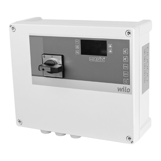
• 2 inputs for thermal winding monitoring with bimetallic temperature sensor. Connection of PTC Fig. 1.: Overview of operating components sensors is not possible! Control panel with 1 Main switch buttons 3.4.2. Outputs 2 LED indicators • 1 potential-free contact for SSM WILO SE 04-2015 V05 DIN A4... -
Page 10: Type Key
Claims made after this date cannot be *"S" version with shock-proof/CEE16 plug recognised. Damage to parts must be noted on the freight documentation. 3.5. Type key Example: Wilo-Control MS-L 2x4kW-M-DOL-S 4.2. Transport Micro Control switchgear for fixed speed pumps Only the packaging used by the manufacturer or supplier may be used for transport. This normally... -
Page 11: Return Delivery
Draw the four holes on the assembly area. • Drilling distances (WxH): 268x188 mm The following information must be observed • Observe the information on the underside of when installing the switchgear: the switchgear too! Drill the holes according to the specifications for • The work must be carried out by a qualified electrician. the fixation materials used. WILO SE 04-2015 V05 DIN A4... -
Page 12: Electrical Connection
• Observe the installation and operating in- ed to the earth terminal (;). structions for the connected pump and signal • DIP switch 2: DIP position "1": OFF (bottom transmitters. position) • The mains connection current and voltage must be as stated on the rating plate. Installation and operating instructions Wilo-Control MS-L 2x4kW... - Page 13 Connect wires as follows to the motor protection for the relevant pump (P1, P2): Connect the wires to the terminals for the corre- • Pump connection 1~230 V, 3-core cable: sponding pump at the terminal strip: • Terminals: 4/T2 (L), 6/T3 (N) • Pump 1: Terminal 1 and 2 (WSK-P1) • The protective earth conductor (PE) is connect- • Pump 2: Terminal 3 and 4 (WSK-P2) ed to the earth terminal (;). WILO SE 04-2015 V05 DIN A4...
- Page 14 The function can be switched on/off via DIP switch 1, DIP 6: Connect the wires according to the required function at terminals 11, 12 and 13 of the termi- • "ON" position: Pump kick on nal strip. • "OFF" position: Pump kick off (factory setting) Installation and operating instructions Wilo-Control MS-L 2x4kW...
-
Page 15: Operation And Function
This reduces the running ed continuously when mains voltage is present. time of the rechargeable battery. Counter reset must be carried out by Wilo Cus- tomer Service. 6. Operation and function The function and the desired interval can be... -
Page 16: Button Lock
When the button lock is active, the buzzer can areas is strictly prohibited. be switched off and the collective fault signal relay deactivated during an alarm signal with the Buzzer OFF/Reset button. Faults cannot be acknowledged nor can the control be released. Installation and operating instructions Wilo-Control MS-L 2x4kW... -
Page 17: Activating The Switchgear
Follow the instructions under “Ro- reached, the peak-load pump is switched off im- tation control" for this. mediately. The "Pump operation" LED goes out. • "Base-load pump OFF" level: If the off level is reached, the follow-up time set is active. During 7.4. Rotation control of connected three-phase AC motors the follow-up time, the "Pump operation" LED flashes. Once the follow-up time has expired, In the factory, a switchgear for a clockwise the base-load pump switches off and the "Pump rotating field is checked for correct direction of operation" LED goes out. rotation and set. WILO SE 04-2015 V05 DIN A4... -
Page 18: Behaviour During Operation
Make sure that the ambient conditions are ob- served accordingly: • More information about proper disposal can be • Ambient/operating temperature: -30 ... +60 °C obtained from the municipal authorities, the Installation and operating instructions Wilo-Control MS-L 2x4kW... -
Page 19: Maintenance And Repair
• Visual inspection of individual components LED lights up yellow 9.2. Maintenance work Cause: The set service interval has expired Prior to maintenance work, the switchgear must Solution: Perform maintenance on the unit and have be switched off as described under "Temporary the counter reset by Wilo Customer Service shutdown". Maintenance work may only be car- LED flashes yellow ried out by qualified persons. Cause: The monitored operating parameters have been exceeded 9.2.1. Clean the switchgear Solution: Check the settings on the unit and have Use a damp cotton cloth to clean the switchgear. -
Page 20: Fault Memory
1 Manual Mode and Stop buttons. 0.1380 0.0830 10.4. Further steps for troubleshooting If the points listed here do not rectify the fault, 0.2100 contact Wilo Customer Service. They can help you 0.1240 as follows: 0.0740 • Telephone and/or written support from Wilo Customer Service •... - Page 21 European standards: EN 60204-1 ainsi qu’aux normes européennes harmonisées suivantes: EN 61000-6-1:2007 EN 61000-6-2:2005 EN 61000-6-3:2007 EN 61000-6-4:2007 Dortmund, 28.03.2013 Holger Herchenhein WILO SE Quality Manager Nortkirchenstraße 100 44263 Dortmund Germany Document: 2117859.1 CE-AS-Sh. Nr.: 2533606...
- Page 22 WILO SE Nortkirchenstraße 100 44263 Dortmund Germany T +49 (0)231 4102-0 F +49 (0)231 4102-7363 wilo@wilo.com Pioneering for You www.wilo.com...
Need help?
Do you have a question about the Control MS-L 2x4kW Series and is the answer not in the manual?
Questions and answers