AAT C-max User Manual
Stair climbing system
Hide thumbs
Also See for C-max:
- User manual (40 pages) ,
- Translation of the original user manual (40 pages)
Table of Contents
Advertisement
Quick Links
Advertisement
Table of Contents

Related Manuals for AAT C-max

Summary of Contents for AAT C-max
- Page 1 -max Stair Climbing System Translation of the original user’s manual...
- Page 2 -max CE Declaration of conformity The company AAT Alber Antriebstechnik GmbH herewith declares that the -max were developed and manufac- products of the stair climbing system tured in concordance with the current regulations of the European Union, EEC Guidelines 93/42/EWG.
-
Page 3: Table Of Contents
-max Table of contents CE Declaration of conformity ... . Table of contents ....General information . - Page 4 -max Accessories ......Battery pack ....Exchange the battery pack .
-
Page 5: General Information
The c-max is capable of climbing stairs up to a step heigth of 21 cm. The mi- nimum depth of the step’s surface must be 14 cm, regardless of the type of stairs (regular straight stairs or winding stairs). -
Page 6: Description Of The Product
Only authorized operators may use the s-max. Therefore never leave the s-max unattended. Please do not use the c-max in the rain or generally in wet conditions Driving on level ground due to the following potential safety hazards, e.g. danger of slipping, restricted braking effect etc. -
Page 7: Features Of The -Max
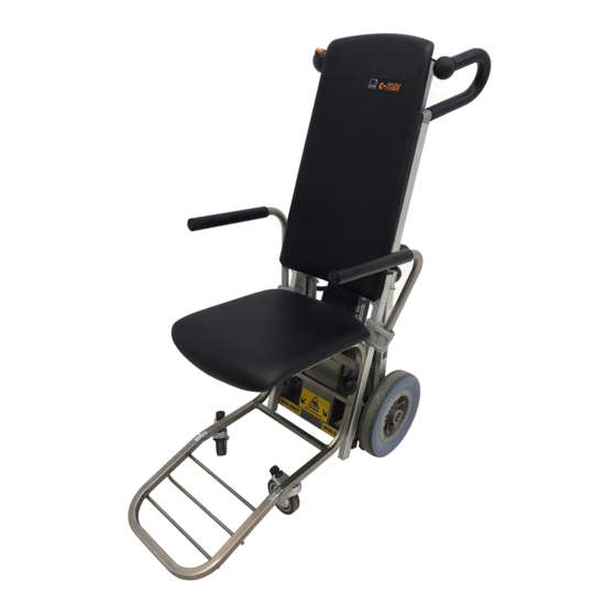
-max -max Features of the 1 = control unit 2 = handles, adjustable 3 = back rest 4 = arm rest, swivels out 5 = C-part plus seat 6 = climbing frame 7 = foot rest, folds in 8 = main wheel 9 = lever with chain drive 10 = climber and climbing foot 11 = safety brake... -
Page 8: Assembly
-max Assembly -max by means of several fix- With a few movements you can assemble the tures and tightening knobs. Disassembly is just as easy. Attach the back rest to the climbing frame Put the back rest onto the guide pins on top of the climbing frame. Affix the back rest Fix the back rest tightly to the climbing frame with the two tightening knobs. -
Page 9: Helix Cable
-max Helix cable Put the connector of the helix cable into its socket located on the power unit's housing. Lock the connector by pushing up the latching. Be catious that neither connector nor socket become wet by e.g. wa- ter or snow - this may cause a short circuit between pins and result in severe malfunction of the system Attach the battery pack Push the battery pack into its fixture by means of the guiding pins on top of... -
Page 10: Arm Rests
-max Arm rests Insert arm rests on both sides. Please always make sure that the stop bolts snap in their appropriate notches. Handles Adjust handles to the appropriate height Πon both sides (see chapter 6.7) then fasten them with the tightening knobs . After adjusting the handles, always make sure that they are securely fastened. -
Page 11: Safety Instructions
The potential steps downward, therfore, are not limited. Transport: Make sure you never lift the device at the frame (see chapter 6.13). Also please always turn off the c-max for transportation! -
Page 12: Operation
-max Operation Maximum lifting capacity Please make sure that the maximum lifting capacity is not exceeded. Control light After turning on the device, the control light Πshould light up and stay on. Flashing of the control light indicates malfunction. Further information on malfunction you find in chapter 6.1.4 Helix cable connector Check whether the connector of the helix cable ... -
Page 13: Instructions For Operation
-max Instructions for operation Before we get to the actual instructions for operation, we would like to intro- -max’s most important components to you: duce the Operational components The control unit is situated on the right handle and consists of an UP/DOWN switch Œ, a speed control , a safety chip for the engine immobiliser Ž... -
Page 14: Single Step Control
-max 6.1.5 Control light to indicate malfunction -max the green control light (LED) lights up and re- After turning on the mains lit, which indicates that the stair climbing system is in order and rea- dy to use. Potential malfunction is indicated by a light diode. After a period of 3 se- conds each time a blinking signal is repeated. -
Page 15: Climbers
-max is granted. Important: If the required brake effect is not guaranteed, you may, -max any more. Please contact under no circumstances, use the your local AAT Alber dealer or the manufacturer immediately. - Page 16 -max -max Transportation of people with the -max was developed to be operated by one person. Al- Please note that the ways use both hands when using the device. -max on level ground, slopes and Please practice driving with the climbing up- and downstairs at first without a person sitting in the chair! Whenever you practice, please make sure that nobody is stan- -max on a...
-
Page 17: Operation On Level Ground
-max Operation on level ground After the person has been properly seated, you may transport him or her ef- fortlessly on level ground (see picture) -max backwards is much easier Passing over thresholds pulling the than pushing it forwards over them. Adjust the handles For climbing stairs or driving on slopes, comfortably and safely, adjust the height of the handles approximately to the level of the operator's shoulders. -
Page 18: Tilting The Stair Climbing System
-max Tilting the stair climbing system -max, which can be To drive on slopes or to climb stairs you must tilt the done easily by means of the climbers. -max by pressing the ON/OFF switch. Turn on the Press the UP/DOWN switch direction DOWN until the climbers lift the main wheels at least 1-2 cm off the floor (see picture). -
Page 19: Climbing Upstairs
-max 6.10 Climbing upstairs Please always practice climbing stairs without a person and by acti- vating the single step mode plus the lowest climbing speed. The climbing process can be accomplished quickly and without problems if you adhere closely to the following instructions. A tip before you start: -max slightly towards During the climbing process always pull the... - Page 20 -max The climbing process takes place in two intervals. The first interval starts by pressing the UP/DOWN switch, direction UP. The climbing process begins here with the power unit initiating the movement of the climbers downward Œ After the climbers reach the floor, they assume the load of the main wheels while the main wheels and the frame Ž...
- Page 21 -max The first interval is finished when the main wheels touch down on the next higher step and resume the load of the climbers. 10. The second interval begins by pulling in the climbers . It is finis- hed when the climbers reach their topmost position. If you activated the single step mode, the climbing process ends at this point.
-
Page 22: Climbing Downstairs
-max 6.11 Climbing downstairs Please always practice climbing downstairs without a person, and by activating the single step mode plus the lowest speed. The descending process can be accomplished quickly and without pro- blems, if you adhere carefully to the following instructions. Adjust the handles to the appropriate height (see chapter 6.7) -max by pressing the ON/OFF switch. - Page 23 -max Press the UP/DOWN switch, direction DOWN, and the descending process begins. The power unit moves the climbers Ž down. 10. When the climbers reach the next lower step , they resume the load of the main wheels, while those plus the climbing frame are lif- ted off the higher step Î...
- Page 24 -max 11. Now the main wheels and the climbing frame are moved forward ‘ Then the main wheels plus the climbing frame are lowered ’ by pul- ling up the climbers “ until... 12..the main wheels touch down on the next step (see picture). If you activated the single step mode, the climbers are pulled in enti- rely and then the descending process ends at this point.
-
Page 25: Laying The -Max On The Stairs
Transport You may remove the seat of the c-max for transportation (see chapter 3). Should you prefer to transport the c-max with the seat, please lift it at both the grip and the seat. Make sure you never lift the device at the frame! -
Page 26: Accessories
The quick release battery pack should always be connected to the charger to extend its durability (see chapter 8.4). Please exclusively use the AAT Alber charger to charge your battery pack. Charging cable for your vehicle... -
Page 27: Care And Maintenance
New user If the device goes to a new user, we recommend a safety check. Charger Please exclusively use the AAT Alber charger to charge your battery packs. 8.2.1 Automatic charger -max comes with the automatic charger. The charging cable's plug Œ... -
Page 28: Battery Pack
Thus, do avoid a total discharge, by recharging the batteries whenever possible! Charging your batteries is taking good care of them. Return dead batteries to AAT Alber Antriebstechnik GmbH or take them to particular recycling places where they can be recycled appropriately. -
Page 29: Charging The Battery Pack
-max Charging the battery pack Remove the battery pack from the power unit (see chapter 7.2) Connect the charger's plug to the socket on the battery pack. Re- -max can be discharged or recharged member: The batteries of your in any possible position. -
Page 30: Check Brake Lining
Please check the thickness of the safety brakes’ lining regularly. The mini- mum thickness Œ is 1 mm. In case the lining is thinner than 1 mm, the li- ning must be exchanged on both sides. Please contact AAT Alber Antriebstechnik GmbH or your local dealer. -
Page 31: Cleaning
The s-max and its battery pack are products of long durability. However, if your s-max is old and has reached the end of its lifespan you may return its components to AAT Alber Antriebstechnik GmbH or your local dealer to be recycled. -
Page 32: Warranty And Liability
-max Warranty and liability Warranty AAT Alber Antriebstechnik GmbH grants a warranty of two years for all its -max including all its accessory parts (with the exception products of type of the sealed lead acid batteries). The warranty begins at the date of purcha- se and covers failure of material and errors in manufacturing. - Page 33 -max...
- Page 34 -max...
- Page 35 -max...
- Page 36 -max AAT Alber Antriebstechnik GmbH Postfach 10 05 60 · D-72426 Albstadt Tel.: +49 - 74 31 - 12 95 0 · Fax.: +49 - 74 31 - 12 95 35 Email: info@aat-online.de · www.aat-online.de...
Need help?
Do you have a question about the C-max and is the answer not in the manual?
Questions and answers