Table of Contents
Advertisement
Quick Links
Advertisement
Table of Contents

Related Manuals for ECOVOLVE ED800


Summary of Contents for ECOVOLVE ED800
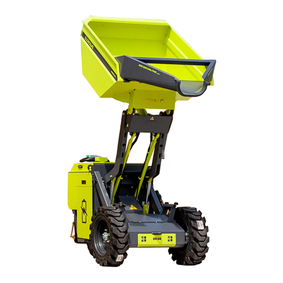
- Page 1 Battery Hi-Tip Dumpers ED800/1000/1500 OWNER’S MANUAL...
-
Page 2: Table Of Contents
CONTENTS CONTENTS 1 Introduction Transportation ................Transporting the electric dumper . - Page 3 Technical data sheet US ..............ED800 Parts list Exploded front view parts list .
-
Page 4: Introduction
Servicing should only be carried out by qualified personnel approved by the manufacturer (specialists). This material is proprietary to Ecovolve, and is not to be reproduced, used, or disclosed except in accordance with written authorisation from Ecovolve. Each new user must read the Operator’s Hand Book before operating any Ecovolve truck for the first time. - Page 5 Despite the utmost care, we cannot rule out deviations from drawings or dimensions, by improper use. Ecovolve Ltd will not be responsible for such loss. If you want to use an computing errors, printing errors or incompleteness in this operator’s manual. Therefore, we...
-
Page 6: Safety
It is therefore far more maneuverable than a conventional dump truck. The Ecovolve Range are intended to transport and empty materials within the specified load capacity in normal operating conditions. It is the operators responsibility to use sound judgment to assess whether a ground material is compatible with use of the Truck. -
Page 7: Safety Guidelines
Safety Features Specified settings may only be changed with the approval of the manufacturer. � Ecovolve has introduced many safety features to make the Ecovolve range safe and user friendly. An overview of these are as follows: Danger Area People must not stand in the danger area of an industrial truck. Danger areas are those areas Three operating speeds: Creeper for when the skip is raised (under 1 km), Walking (under �... - Page 8 2. SAFETY 2. SAFETY Safety guidelines Safety guidelines Driving Routes and Tip Over OPERATORS PERSONAL PROTECTIVE EQUIPMENT (PPE) Stability is guaranteed if the electric dumper is used correctly according to specified targets. Driving routes shall be free of objects. � HARD HAT REQUIRED When the instruction for a hard hat is stated, a hard hat Gradients used by the truck cannot exceed a max of 10°.
- Page 9 2. SAFETY 2. SAFETY Safety guidelines Safety guidelines SAFETY SYMBOL EXPLANATION SAFETY SYMBOL EXPLANATION CAUTION! Indicates a hazardous situation which, if not avoided, could result in moderate injury. ELECTRICAL WARNING! Indicates a hazardous situation which, if not avoided, could result in death or serious injury. CRUSH PARTS WARNING! Indicates a hazardous situation which, if not avoided, DANGER!
-
Page 10: Overview
OVERVIEW Identification plate NOTE The CE mark confirms compliance with the EC machinery directives and with all regulations applicable to the Ecovolve hi tip electric dumper. Identification pate 1 Nameplate 2 Manufacturer 3 Model number 4 Serial no/year of manufacture... -
Page 11: Operators Platform And Safety Rails
3. OVERVIEW 3. OVERVIEW operators platform and safety rails Controls Operators platform and safety rails Controls CAUTION CAUTION The following section is a brief overview of the The following section is a brief overview of the operators platform and safety rails. dashboard controls. - Page 12 3. OVERVIEW 3. OVERVIEW Controls Controls CAUTION CAUTION The following section is a brief overview of the The following section is a brief overview of the dashboard controls. All operators must read and tiller head controls. All operators must read and understand the operating instructions in section understand the operating instructions in section 4 of this manual before operating the truck.
-
Page 13: Operation
Information Electric hi tip dumper important information All electric products from Ecovolve are very user friendly machines to drive and operate. They are carefully manufactured with high quality components which ensure a long trouble free life. Whilst being designed, many safety features were considered and built in as standard to protect the operator and fellow work colleagues. -
Page 14: Switching The Dumper On And Off
4. OPERATION 4. OPERATION Driving and operation Driving and operation Driving and operation Operators platform Switching the dumper on and off The truck has a two position platform for the operator to stand on when operating the truck. � WARNING In the raised position the operator can walk behind the dumper (fig 1). -
Page 15: Forward Travel
4. OPERATION 4. OPERATION Driving and operation Driving and operation Forwards travel Operating speeds Pull out the emergency stop button, insert the key and start the truck. The dumper has three operating speeds. � For forward motion the traction paddles are pressed upwards and for reverse motion the Creeper mode under 1 kph: The truck automatically selects creeper mode when the high tip �... -
Page 16: Lights
4. OPERATION 4. OPERATION Driving and operation Driving and operation Lights Hi tip skip operation The truck is equipped with both front and rear facing lights (fig 1 and fig 2). � DANGER The lights can be turned on and off using the switch on the dash (fig 3). CRUSH PARTS There is a risk of becoming trapped between moving parts due to the skip lifting arm. -
Page 17: Battery Discharge
4. OPERATION 4. OPERATION Driving and operation Battery Battery Parking the truck In the interest of safety, parking the truck is the operators responsibility. � Battery discharge indicator The operator must ensure to park the truck in a safe and secure manner and not be in �... -
Page 18: Charging
Lock the charging compartment door and return the key to the ignition on the dash. Power on the truck with the key to recommence work after the charge is All electric trucks from Ecovolve are fitted with an internal automatic complete. - Page 19 4. OPERATION 4. OPERATION Charging Charging Charging QuiQ 1000 operating instructions Delta Q IC1200 Battery charger Replaces QuiQ1000 in ED1000 model from June 2018 The QuiQ 1000 is replaced by the Delta Q IC1200 in the ED1000 models from june 2018 Display icons 1.
-
Page 20: Transportation
The truck has two lifting points and five anchor points which are used to lift and secure the � The Ecovolve range are all easily transportable. It is comparatively lightweight for its capacity and machine when transporting. can be loaded on to a vehicle with a load rating of 1300kg minimum. The operator’s platform and Use certified slings and chains to secure the truck when being transported. -
Page 21: Dailychecklist
4. OPERATION 4. OPERATION Cleaning Daily checklist Cleaning the electric dumper DAILYCHECKLIST Cleaning guidelines DANGER Failure to follow the daily checklist could result in a hazardous CAUTION situation which could result in serious injury and damage to the truck. Do not power wash the machine. Possibility of causing damage or destruction of electrical Always carry out the daily checklist before operating the truck. -
Page 22: Servicing
5. SERVICING 50 Hour inspection checklist 50 WORKING HOUR INSPECTION The following items must be serviced at the specified working hours. The work must be completed by a competent technician. Failure to do this will reduce or void your warranty! The Truck has two Vehicle Identification Information items that are required and can be found on the rear drive unit and chassis as shown below (fig 1 and fig 2). -
Page 23: Chassis And Frame
5. SERVICING 5. SERVICING 50 Hour inspection checklist 50 Hour chassis and frame inspection Chassis and frame 50 WORKING HOUR INSPECTION SERVICE ITEMS DATE COMPLETED BY Chassis 1. Check all safety symbols and décor is clearly visible. 2. Check operator safety rails and platform. Steering &... -
Page 24: Wheels
5. SERVICING 5. SERVICING 50 hour wheels inspection 50 hour steering and dashboard inspection Wheels Steering and dashboard Steering & Check all steering functions and dashboard switches. Wheels 1. Check wheel nuts are tight. Inspect wheels for wear and damage. Dashboard 2. -
Page 25: Lubrication
If required, apply grease to each point with suitable grease using a grease gun (fig 1 to fig 8). � The Ecovolve range requires just one pump of a standard grease gun. Clean surplus grease from point with a damp cloth and reapply dust cap. -
Page 26: Hydraulic System
Always use the same original type of oil when topping up or changing. � The Ecovolve range uses HYD 46 Hydraulic oil. Tank capacity is 2.8 litres � DANGER... -
Page 27: Rear Drive Unit
5. SERVICING 5. SERVICING 50 hour hydraulic system inspection 50 hour rear drive unit inspection Rear drive unit 3. Check oil level When checking the hydraulic oil level protective gloves and glasses must be worn. � The skip MUST be in the lowered position with all hydraulic cylinders closed. Engage �... -
Page 28: Braking System
5. SERVICING 5. SERVICING 50 hour breaking system inspection 50 hour charging system inspection Braking system charging system Braking Electric Inspect brake performance and adjust as needed. Check charging system and cable. system Charging CAUTION CAUTION Indicates a hazardous situation which, if not avoided, could Indicates a hazardous situation which, if not avoided, could result in moderate or serious injury. -
Page 29: Working Hour Service
The following items must be serviced at the specified working hours. Proof must be submitted to Ecovolve that this service has been completed by a competent technician. To do this complete this form and submit it to Ecovolve including all relevant vehicle identification information at www.ecovolve.eu. - Page 30 The following items must be serviced at the specified working hours. Proof must be submitted after a long operating time, oil in the unit may be hot; please wear special to Ecovolve that this service has been completed by a competent technician. To do this gloves.
-
Page 31: Chassis And Frame
5. SERVICING 5. SERVICING 500 hour chassis and frame service 500 hour wheels service Chassis and frame Wheels 1. Check wheel nuts are at proper torque. Chassis Inspect for any damage to the chassis and bodywork. Wheels 2. Inspect wheels for wear and damage. Inspect any load bearing parts and joints. -
Page 32: Steering And Dashboard
5. SERVICING 5. SERVICING 500 hour steering and dashboard service 500 hour steering and dashboard service Steering and dashboard Steering and dashboard inspection Steering & Check all steering functions & switches. Dashboard CAUTION Ensure when testing the steering system that the test area is free from obstructions and pedestrians. -
Page 33: Lubrication
If required, apply grease to each point with suitable grease using a grease gun (fig 1 to fig 8). � The Ecovolve range requires just one pump of a standard grease gun. Clean surplus grease from point with a damp cloth and reapply dust cap. -
Page 34: Hydraulic System
Always use the same original type of oil when topping up or changing. � The Ecovolve range uses HYD 46 Hydraulic oil. Tank capacity is 2.8 litres � DANGER... -
Page 35: Rear Drive Unit
5. SERVICING 5. SERVICING 500 Hour rear drive unit service 500 Hour breaking system service Rear drive unit service Braking system Rear Drive 1. Inspect for leaks, defects or unusual noise in the rear drive unit. Braking 1. Inspect brake performance and adjust as needed. 2. -
Page 36: Battery Care
Battery Care The following items must be serviced at the specified working hours. to Ecovolve that this service has been completed by a competent technician. To do this Proof must be submitted to Ecovolve that this service has been complete this form and submit it to Ecovolve including all relevant vehicle identification completed by a competent technician. -
Page 37: Rear Drive Unit Oil Change
Record the necessary information as shown and submit to Ecovolve at � Record Result. www.ecovolve.eu. A copy of this form is included at the end of this manual. � The oil level must be checked again after a short operating period. Whether necessary top up with same oil till the correct level. - Page 38 5. SERVICING 5. SERVICING Service and inspection forms Service and inspection forms DAILYCHECKLIST WARNING Failure to follow the daily checklist could result in a hazardous situation which could result in serious injury and damage to the truck. Always carry out the daily checklist before operating the electric dumper. If any item on the daily checklist fails, contact your site supervisor and DO NOT operate the truck before doing so..
- Page 39 5. SERVICING 5. SERVICING Service and inspection forms Service and inspection forms 50 WORKING HOUR INSPECTION 50 WORKING HOUR INSPECTION SERVICE ITEMS The following items must be serviced at the specified working hours. The work must be DATE COMPLETED BY completed by a competent technician.
- Page 40 The following items must be serviced at the specified working hours. Proof must be submitted to Ecovolve that this service has been completed by a competent technician. To do this to Ecovolve that this service has been completed by a competent technician. To do this...
- Page 41 6. TECHNICAL DATA EU Technical data sheet TECHNICAL DATA...
- Page 42 6. TECHNICAL DATA 6. TECHNICAL DATA US Technical data sheet ED800 Parts list ED800 ELECTRIC DUMPER ED800 Electric Dumper exploded front view parts list...
- Page 43 6. TECHNICAL DATA 6. TECHNICAL DATA ED800 Parts list ED800 Parts list ED800 Electric Dumper exploded rear view parts list...
- Page 44 6. TECHNICAL DATA 6. TECHNICAL DATA ED800 Parts list ED800 Parts list steering assembly tiller head parts list...
- Page 45 6. TECHNICAL DATA 6. TECHNICAL DATA ED800 Parts list ED800 Parts list Operators platform and safety arm parts list Operators platform and safety arm parts list Operators platform Safety rail...
- Page 46 6. TECHNICAL DATA 6. TECHNICAL DATA ED800 Parts list ED800 Parts list Hydraulic system parts list Tiller head parts list 18424081 18424082 SWITCH - GREEN SWITCH HARE/TORTOISE GREEN - ON-OFF 18424043 18424050 COVER/HOUSING LOWER HOUSING GREY GREY 18434035 18434040 (INTERNAL)
- Page 47 6. TECHNICAL DATA 6. TECHNICAL DATA ED800 Parts list ED800 Parts list Hydraulic system parts list Electrical system parts list...
- Page 48 6. TECHNICAL DATA 6. TECHNICAL DATA ED800 Parts list ED800 Parts list Electrical system parts list Drive unit parts list...
- Page 49 6. TECHNICAL DATA 6. TECHNICAL DATA ED800 Parts list ED1000 Parts list ED1000 ELECTRIC DUMPER Drive unit parts list ED1000 Electric Dumper exploded front view parts list...
- Page 50 6. TECHNICAL DATA 6. TECHNICAL DATA ED1000 Parts list ED1000 Parts list ED1000 Electric Dumper exploded ITEM PART NUMBER DESCRIPTION QTY. rear view parts list E1016-2007 Side Panel Assy (RHS) E1016-5601 Steering Assembly E1016-2511 Tilt Hyd. Cylinder Assy. E1016-2516 Turn buckle E1016-2513 Hyd.
- Page 51 6. TECHNICAL DATA 6. TECHNICAL DATA ED1000 Parts list ED1000 Parts list steering assembly tiller head parts list ITEM PART NUMBER DESCRIPTION QTY. E1016-5601 Steering Assembly E1016-2012 Safety Bar (RHS) Weldment E1016-3002 Vertical electric wheels EBv570.000C-B KILIT_3 Charging Panel Lock E1016-2013 Safety Bar (LHS) Weldment E1016-1502...
- Page 52 6. TECHNICAL DATA 6. TECHNICAL DATA ED1000 Parts list ED1000 Parts list Operators platform and safety arm parts list Operators platform and safety arm parts list Operators platform ITEM NO. PART NUMBER DESCRIPTION QTY. E1016-1013 Step Rear E1016-1036 Pivot Bolt, Step and Safety Bar E1016-1020 Step Spring Post M8 Lock Nut...
- Page 53 6. TECHNICAL DATA 6. TECHNICAL DATA ED1000 Parts list ED1000 Parts list Hydraulic system parts list Tiller head parts list 18424081 18424082 SWITCH - GREEN SWITCH HARE/TORTOISE GREEN - ON-OFF 18424043 18424050 COVER/HOUSING LOWER HOUSING GREY GREY 18434035 18434040 (INTERNAL) EMERGENCY REVERSE BLUE BUTTON - RED...
- Page 54 6. TECHNICAL DATA 6. TECHNICAL DATA ED1000 Parts list ED1000 Parts list Hydraulic system parts list Electrical system parts list ITEM PART NUMBER DESCRIPTION QTY. E1016-2511 Tilt Hyd. Cylinder Assy. E1016-2516 Turn buckle E1016-2512 Hyd. Lift Cylinder assy Vibo Power pack Hydraulic Pump VIBOSolenoidValve E1016-1046...
- Page 55 6. TECHNICAL DATA 6. TECHNICAL DATA ED1000 Parts list ED1000 Parts list Electrical system parts list Drive unit parts list ITEM PART NUMBER DESCRIPTION QTY. Battery-200Amp NSB/210FT BLUE+ DeltaQ IC1200-A1 Delta Q - Battery Charger E1016-3003 Rear LED Lamp E1016-1119 Clear glass for Rear Lights 220V PEW163CS 220V Socket-angle_box...
- Page 56 6. TECHNICAL DATA 6. TECHNICAL DATA ED1000 Parts list ED1500 Parts list ED 1500 ELECTRIC DUMPER Drive unit parts list ED 1500 Electric Dumper exploded front view parts list...
- Page 57 6. TECHNICAL DATA 6. TECHNICAL DATA ED1500 Parts list ED1500 Parts list ED1500 Electric Dumper exploded rear view parts list ITEM Front End PART NUMBER DESCRIPTION BOM/QTY. E1516-5001 Chassis Weldment EVO-0151 Front Tyre (Trelleborg SK800 E1516-2517 27x8.5-15) E1516-1053 Front Wheel Rim E1516-5009 Safety Arm (RHS) E1516-1037...
- Page 58 6. TECHNICAL DATA 6. TECHNICAL DATA ED1500 Parts list ED1500 Parts list Steering assembly and tiller head parts list Rear End ITEM NO. PART NUMBER DESCRIPTION BOM/QTY. E1516-1522 Top Cover Plate E1516-2508 Rubber Buffer M5x25x16 E1516-1540 Control Consol E1516-1401 Battery Box Front Plate E1516-5009 Safety Arm (RHS) E1516-2501...
- Page 59 6. TECHNICAL DATA 6. TECHNICAL DATA ED1500 Parts list ED1500 Parts list Operators platform and safety rails parts list Operators platform and safety rails parts list Safety rails ITEM PART NUMBER DESCRIPTION QTY. E1516-1071 Safety Bar (RHS) E1516-1042 Step D Washer E1516-1039 Boss, Plunger, Safety Bar E1516-1073...
- Page 60 6. TECHNICAL DATA 6. TECHNICAL DATA E1500 Parts list ED1500 Parts list Hydraulic system parts list Tiller head parts list 18424081 18424082 SWITCH - GREEN SWITCH HARE/TORTOISE GREEN - ON-OFF 18424043 18424050 COVER/HOUSING LOWER HOUSING GREY GREY 18434035 18434040 (INTERNAL) EMERGENCY REVERSE BLUE BUTTON - RED...
- Page 61 6. TECHNICAL DATA 6. TECHNICAL DATA ED1500 Parts list ED1500 Parts list Hydraulic system parts list Electrical system parts list ITEM PART NUMBER DESCRIPTION QTY. E1516-5008 Tapered Locking Collar/Shaft Set E1516-5006 Turn Buckle E1516-2512_asm Hyd Cylinder - Arm lift E1516-2511_asm Hyd Cylinder - Tilt lift E1516-2510 Vibo Hydraulic Power pack...
- Page 62 6. TECHNICAL DATA 6. TECHNICAL DATA ED1500 Parts list ED1500 Parts list Electrical system parts list Drive unit parts list ITEM PART NUMBER DESCRIPTION QTY. E1516-3004 Curtis Joystick vaf11150 Battery Charge Level Guage 42464 60mm Dia E Stop 22232_01 Toggle Switch SM-SL012 Beacon light flash - Amber SM-SL012 E1516-3003...
- Page 63 6. TECHNICAL DATA ED1500 Parts list Drive unit parts list TROUBLESHOOTING...
- Page 64 7. TROUBLESHOOTING 7. TROUBLESHOOTING Delta Q 1200 battery charger Delta Q 1200 battery charger Delta Q IC1200 battery charger fault and error list Delta Q IC1200 charging profiles Delta-Q IC SeriesUserManual Charger Error & Fault CodesTable Charging Profiles Code Description Solution The IC Series charger contains up to 25 selectable charging profilesstored in itsinternal memory tocharge batteries.
- Page 65 Green Ifsolid:Chargingcompleteand maintenance mode isactive. Ifflashing: Short:<80% Charge. 7. TROUBLESHOOTING 7. TROUBLESHOOTING Long: >80% Charge. Delta Q QuiQ1000 battery charger Curtis 1232/34 AC controller When batteryisnotconnected:Charge Profile(AlgorithmNumber)display Ifflashing:Reducedpowermode.Low AC voltageorhigh internalcharger Amber temperature. Delta Q QuiQ1000 battery charger fault and error list Curtis 1232/34 AC controller troubleshooting Ifflashing:Chargingerror.Resetchargerpowerand refertoTroubleshooting...
- Page 66 7. TROUBLESHOOTING 7. TROUBLESHOOTING Curtis 1232/34 AC controller Curtis 1232/34 AC controller Summary of LED Display Formats PROGRAMMER LCD DISPLAY CODE POSSIBLE CAUSE SET / CLEAR CONDITIONS EFFECTOFF AUL T Thetwo LEDshavefour different displaymodes,indicating the type of information they areproviding. Controller Overcurrent 1.
- Page 67 7. TROUBLESHOOTING 7. TROUBLESHOOTING Curtis 1232/34 AC controller Curtis 1232/34 AC controller PROGRAMMER LCD DISPLAY PROGRAMMER LCD DISPLAY CODE POSSIBLE CAUSE SET / CLEAR CONDITIONS CODE POSSIBLE CAUSE SET / CLEAR CONDITIONS EFFECTOFF AUL T EFFECTOFF AUL T Severe KSI Overvoltage 1.
- Page 68 7. TROUBLESHOOTING 7. TROUBLESHOOTING Curtis 1232/34 AC controller Curtis 1232/34 AC controller PROGRAMMER LCD DISPLAY PROGRAMMER LCD DISPLAY CODE POSSIBLE CAUSE SET / CLEAR CONDITIONS CODE POSSIBLE CAUSE SET / CLEAR CONDITIONS EFFECTOFF AUL T EFFECTOFF AUL T Motor Open 1.
- Page 69 7. TROUBLESHOOTING 7. TROUBLESHOOTING Curtis 1232/34 AC controller Curtis 1232/34 AC controller PROGRAMMER LCD DISPLAY PROGRAMMER LCD DISPLAY CODE POSSIBLE CAUSE SET / CLEAR CONDITIONS CODE POSSIBLE CAUSE SET / CLEAR CONDITIONS EFFECTOFF AUL T EFFECTOFF AUL T Stall Detected 1.
- Page 70 7. TROUBLESHOOTING 7. TROUBLESHOOTING Curtis 1232/34 AC controller Curtis 1222 Steering controller Curtis 1222 Steering controller PROGRAMMER LCD DISPLAY CODE POSSIBLE CAUSE SET / CLEAR CONDITIONS EFFECTOFF AUL T Troubleshooting a fault VCL/OS Mismatch 1. The VCLsoftware in the controller Set:VCLand OS software do not match;...
- Page 71 7. TROUBLESHOOTING 7. TROUBLESHOOTING Curtis 1222 Steering controller Curtis 1222 Steering controller Summary of LED Display Formats FAULT NAME STEER TRACTION CLEAR CODE CANOBJECT POSSIBLE CAUSE SET CONDITIONS FAULT FAULT CONDITION Thetwo LEDshavefour different displaymodes,indicating the type of information they areproviding. ACTION ACTION Hardware Fault...
- Page 72 7. TROUBLESHOOTING 7. TROUBLESHOOTING Curtis 1222 Steering controller Curtis 1222 Steering controller FLASH FAULT NAME STEER TRACTION FLASH FAULT NAME STEER TRACTION CLEAR CLEAR CODE CODE CANOBJECT POSSIBLE CAUSE SET CONDITIONS FAULT FAULT CODE CODE CANOBJECT POSSIBLE CAUSE SET CONDITIONS FAULT FAULT CONDITION...
- Page 73 7. TROUBLESHOOTING 7. TROUBLESHOOTING Curtis 1222 Steering controller Curtis 1222 Steering controller FLASH FAULT NAME STEER TRACTION FLASH FAULT NAME STEER TRACTION CLEAR CLEAR CODE CODE CANOBJECT POSSIBLE CAUSE SET CONDITIONS FAULT FAULT CODE CODE CANOBJECT POSSIBLE CAUSE SET CONDITIONS FAULT FAULT CONDITION...
- Page 74 7. TROUBLESHOOTING 7. TROUBLESHOOTING Curtis 1222 Steering controller Curtis 1222 Steering controller FLASH FAULT NAME STEER TRACTION FLASH FAULT NAME STEER TRACTION CLEAR CLEAR CODE CODE CANOBJECT POSSIBLE CAUSE SET CONDITIONS FAULT FAULT CODE CODE CANOBJECT POSSIBLE CAUSE SET CONDITIONS FAULT FAULT CONDITION...
- Page 75 NB: For every defect detected on the UNIT y o u s h o u l d c o n s u l t B O R G H I S R L info@ecovolve.eu www.ecovolve.eu +353 (0)57 862 6669...
Need help?
Do you have a question about the ED800 and is the answer not in the manual?
Questions and answers