Advertisement
Quick Links
Introduction
Nuaire's MEV-B and MEV-2B surface mounted domestic
extract fans are designed to be installed in the main area to
be served.
Other adjoining rooms can be linked to the unit by rectangular
pvc ducting (by others) and ventilated. A typical installation
would be in a domestic kitchen with secondary ventilation to
toilet(s), utility room(s) and bathroom(s) etc.
The unit is available in single and twin fan models coded B and
2B respectively.
The fans discharge air through a 125mm. dia. spigot on the rear
face. Inlet is through filters located on the either side of the unit
and/or filters in the remote grilles which can easily be removed
for cleaning. Also provided are two subsidiary inlet spigots
which are interchangeable with the inlet grilles in the unit and a
choice of balancing plates which can be introduced under any of
the inlet filters to adjust the airflow from each source.
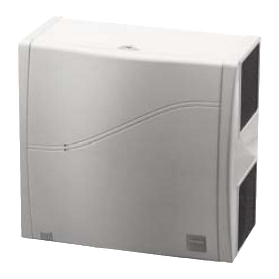
Fig. 1 shows the subsidiary spigots fitted either side.
Two indicator LEDs are provided on the front cover to show fan
status, GREEN for 'Normal / Boost' and RED for 'Fail'.
Figure 1. General view of unit.
The fan is designed to be wired direct to the mains supply
through a fused spur isolator (by others) and run continuously
in the NORMAL mode (which is the low speed or trickle
ventilation setting). The degree of extract from each room served
can be adjusted with the inlet grille balancing plates supplied.
(See page 2).
The unit is provided with adjustment for the trickle (low speed
or NORMAL) and high speed BOOST ventilation as standard.
The NORMAL speed adjustment has a range of 0% to 50%.
The unit is delivered with the NORMAL speed adjustment set to
0%. Note: the NORMAL speed must be set to 25% by the
installer.
An adjustment of 50 -100% is provided for the BOOST duty
setting to reduce performance if necessary.
The unit is delivered with the BOOST speed adjustment set to
100%. (See the adjustments information on page 4).
Coding
MEV-B
Single fan unit.
MEV-2B Twin fan unit (with auto duty sharing and standby).
MEV- B+ Dual fan unit (both fans continuous running).
T: 029 2085 8400 F: 029 2085 8444 E: info@nuaire.co.uk W: www.nuaire.co.uk
MEV-B
Continuous Mechanical Extract
Ventilation Units
Installation and Maintenance
Nuaire Limited Western Industrial Estate Caerphilly United Kingdom CF83 1NA
Duty
Units are available with one or two fans and with the following
free air duty:
100 l/s (MEV-B & MEV-2B).
The MEV-B has a single fan and extracts 100 l/s.
The MEV-2B has two fans and extracts 100 l/s. The unit will
switch to the 'standby' fan in the event of a fan failure.
150 l/s (MEV-B+).
The MEV-B+ has two fans which run continuously and deliver
150 l/s. In the event that one fan fails, the other will still deliver
100 litres as a single fan until the unit is serviced.
Typical mounting arrangements
The unit is designed for surface mounting onto a wall or ceiling.
Figure 2. Fan unit mounting arrangements.
125 circular
ducting (by others)
Fan Ceiling Mounting
Suggested layout arrangements with the fan serving multiple
rooms are shown on page 3.
Installation
IMPORTANT
The installation must be carried out by competent personnel
in accordance with the appropriate authority and conforming
to all statutory and governing regulations, ie IEE, COHSE, HVCA
etc.
Select a solid, non reverberant, mounting position (min. 50mm
clearance from any sidewall and min. 50mm from ceiling for
access to the top cover screw). The unit should be fitted with its
filters and any chosen inlet spigots. All necessary passages for
ductwork from the rear outlet and any inlet spigots as well as
the electrical connections for the main unit and the remote
switch, should be prepared.
It is assumed that compatible ductwork has been installed and
ready to be connected to the 125mm dia rear outlet (and any
rectangular inlet spigot if fitted) of the unit.
Note the unit is not fitted with a backdraught shutter.
In continuous operation a backdraught shutter is not
required.
Isolation - Before commencing work make sure
that the unit is electrically isolated from the mains supply.
Note: internal input socket will be exposed and may be
live with the fan module removed. See isolation notes.
1
The EMC Directive
2004/108/EC
The Low Voltage
directive
2006/95/EC
Wall tube and
fixed louvre
Wall tube and
grille
fixed louvre grille
(by others).
(by others).
Fan Wall Mounting
24. 06. 13. Leaflet Number 671078
Advertisement

Related Manuals for NuAire MEV-B


Summary of Contents for NuAire MEV-B
- Page 1 MEV-2B Twin fan unit (with auto duty sharing and standby). MEV- B+ Dual fan unit (both fans continuous running). Nuaire Limited Western Industrial Estate Caerphilly United Kingdom CF83 1NA T: 029 2085 8400 F: 029 2085 8444 E: info@nuaire.co.uk W: www.nuaire.co.uk 24. 06. 13. Leaflet Number 671078...
-
Page 2: Installation And Maintenance
Installation and Maintenance MEV-B Continuous Mechanical Extract Ventilation Units Cable LED Run & Fail Inlets (both sides) Dimensions access indicators shown with filters fitted Figure 3. Fixing 160 ctrs points Cover fixing screws END VIEW REAR VIEW Optional positions for... - Page 3 Installation and Maintenance MEV-B Continuous Mechanical Extract Ventilation Units Application arrangements 110 x 60 using balancing plates supplied rectangular ducting (by others) Main Room Bathroom Rear outlet En-suite bathroom through outside wall (Grille & filter supplied) Inlet through (Louvre etc not supplied)
- Page 4 Installation and Maintenance MEV-B Continuous Mechanical Extract Ventilation Units Electrical connection Adjusting the Full Speed (boost) All the control functions and adjustments are located on the Electronic Control Module. Please ensure the unit is isolated before The ‘Full Speed’ adjustment is located on the Electronic Control removing the cover.
- Page 5 Foam Filter 772275 Remote Switch 773532 Nuaire can assist you in all aspects of service. Our service department will be happy to provide any assistance required, ELECTRONIC CONTROL MODULE initially by telephone and If necessary arrange for an engineer Single fan MEV-B...
- Page 6 The equipment referred to in this Declaration of Incorporation is supplied by (eg ducting), then guarding to the appropriate standard must be fitted. Nuaire to be assembled into a ventilation system which may or may not include additional components. The electrical installation of the equipment must comply with the requirements The entire system must be considered for safety purposes and it is the of the relevant local electrical safety regulations.
-
Page 7: Customer Details
Standard Assessment Procedure 2005 – Appendix Q Decentralised MEV Installation Guide Installation Guide and Checklist Decentralised Continuous Mechanical Extract Ventilation (Version – 11 February 2011) The Electric Heating and Ventilation Association have developed this guidance and checklist document in partnership with the Residential Ventilation Association (a HEVAC association), BRE and EST. -
Page 8: Installation Guidance
Standard Assessment Procedure 2005 – Appendix Q De-centralised MEV Installation Guide Page 2 of 6 Introduction This document is to be used in support of the SAP Appendix Q scheme which provides tested performance values for De-centralised MEV products. Note that all checklist items must be answered YES in order for the SAP Appendix Q test figures to be used in ‘As built’... - Page 9 Standard Assessment Procedure 2005 – Appendix Q De-centralised MEV Installation Guide Page 3 of 6 Figure 1 Ductwork Visual Guide Source: Approved Document F (England & Wales) 2006 2. Unit Fixing Decision Yes, No or Have the fans been fitted to a stable element of the building fabric (e.g.
- Page 10 Standard Assessment Procedure 2005 – Appendix Q De-centralised MEV Installation Guide Page 4 of 6 Figure 2 Sample Mounting Position Induct In room Through Wall 3. Electrical Connection Decision Yes, No or Has the rating label been verified to establish suitability for the installation strategy and whether an earth is required (e.g.
- Page 11 Standard Assessment Procedure 2005 – Appendix Q De-centralised MEV Installation Guide Page 5 of 6 SECTION 2: COMMISSIONING GUIDANCE 1. System Balancing & Calibration Decision Yes, No or Has the air flow been checked using a proprietary device such as an anemometer (recommended)? Note: the need for background ventilators will depend on the air permeability of the dwelling, and this is not normally known at the design stage.
- Page 12 Standard Assessment Procedure 2005 – Appendix Q De-centralised MEV Installation Guide Page 6 of 6 2. Handover and Control/Maintenance Advice Decision Yes, No or Has the customer been supplied with suitable documentation detailing maintenance and operational requirements? Has the customer been advised not to seal natural air flows from room to room (e.g.
Need help?
Do you have a question about the MEV-B and is the answer not in the manual?
Questions and answers