Delfield F2000 Series Original Instructions Manual
Equipment stands
Hide thumbs
Also See for F2000 Series:
- Service, installation and care manual (20 pages) ,
- Service, installation and care manual (28 pages)
Table of Contents
Advertisement
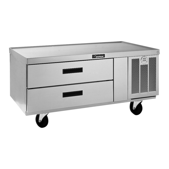
F2000 and F17 Series
Equipment Stands
Original Instructions
Installation, Operation and Maintenance Manual
This manual is updated as new information and models are released. Visit our website for the latest manual.
To assure proper operation a 2" airspace must be maintained between the lowest part of any cooking equipment and
the top of this unit. Cooking equipment must have a barrier (i.e. bottom, drip pan) between its heat source and the top
of the equipment stand. Failure to comply with this could severely damage the equipment stand and void all warranties.
Part Number: 9291457 6/19
Warning
n
Fresh Solutions, Fit for You
Advertisement
Table of Contents

Related Manuals for Delfield F2000 Series


Summary of Contents for Delfield F2000 Series
- Page 1 Fresh Solutions, Fit for You F2000 and F17 Series Equipment Stands Original Instructions Installation, Operation and Maintenance Manual This manual is updated as new information and models are released. Visit our website for the latest manual. Warning To assure proper operation a 2" airspace must be maintained between the lowest part of any cooking equipment and the top of this unit.
- Page 2 Safety Notices Warning This product contains chemicals known to the State Warning of California to cause cancer and/or birth defects or Read this manual thoroughly before operating, installing other reproductive harm. Operation, installation, and or performing maintenance on the equipment. Failure servicing of this product could expose you to airborne to follow instructions in this manual can cause property particles of glasswool or ceramic fibers, crystalline...
-
Page 3: Table Of Contents
Table of Contents Section 1 General Information Model Numbers ........................5 Serial Number Information ....................5 Warranty Information ......................5 Regulatory Certifications ....................5 Standard Models ............................5 Export Options ............................5 Section 2 Installation Location ..........................7 Weight of Equipment ......................8 Clearance Requirements .................... - Page 4 Table of Contents (continued) THIS PAGE INTENTIONALLY LEFT BLANK Part Number: 9291457 6/19...
-
Page 5: General Information
F17C73-E F17C110-E Dry Drawer when calling for parts or service. F17DD32 F17DD73 Warranty Information F17DD46 F17DD81 F17DD54 F17DD96 Visit www.delfield.com/warranty to: F17DD64 Freezer Base • Register your product for warranty. F17FC94P • Verify warranty information. Open Shelf F17OS36 F17OS72 •... - Page 6 General Information Section 1 THIS PAGE INTENTIONALLY LEFT BLANK Part Number: 9291457 6/19...
-
Page 7: Installation
Section 2 Installation Warning DANGER These appliances are to be connected with flexible Installation must comply with all applicable fire and connections for equipotential bonding and connection health codes in your jurisdiction. to services such as electricity supply, water supply, gas supply, and steam supply such that the appliance DANGER can be moved in the direction required for cleaning a... -
Page 8: Weight Of Equipment
Installation Section 2 Weight of Equipment Dimensions Model Shipping Weight Model Length Depth Height Refrigerated Base Refrigerated Base F17C52P, F17C52-E 410lbs (186kg) F17C52P, 52” (132cm) F17C60P, F17C60-E 460lbs (209kg) F17C52-E F17C62P, F17C62-E 460lbs (208kg) F17C60P, 60” (152cm) F17C73P, F17C73-E 500lbs (227kg) F17C60-E F17C75P, F17C75-E 580lbs (263kg) -
Page 9: Capacity
Section 2 Installation Capacity Model Length Depth Height F2973CP 24” (61cm) # Of Drawers F2973P, 73.25” (186cm) 30.93” (79cm) 26” (66cm) 12x20 Pan F2973-E Model Capacity F2975CP 24” (61cm) F2975P, 75.25” (191cm) 30.93” (79cm) 26” (66cm) Refrigerated Base F2975-E F17C52P, F2978CP 24”... -
Page 10: Maximum Cooking Equipment Weight Capacity
Installation Section 2 Maximum Cooking Equipment Weight # Of Drawers Capacity 12x20 Pan Model Capacity Maximum Total Total Unit Cooking Low-Profile Freezer Base Model Drawer Weight Weight Equipment F2660CP, Capacity Weight F2660P Refrigerated Base F2694CP, F17C52P, 1000lbs 410lbs 150lbs 440lbs F2694P F17C52-E (454kg) -
Page 11: Electrical Service
Section 2 Installation Electrical Service Maximum Total Total Unit Cooking Model Drawer Weight Weight Equipment DANGER Capacity Weight Check all wiring connections, including factory Low-Profile Freezer Base terminals, before operation. Connections can become F2660CP, 1500lbs 418lbs 75lbs 1007lbs loose during shipment and installation. F2660P (680kg) (190kg) - Page 12 Installation Section 2 Model Amps H.P. Voltage/Hertz/ Nema Model Amps H.P. Voltage/Hertz/ Nema Phase Plug Phase Plug Refrigerated Base Optional Export Low-Profile Refrigerator Base F17C52P, 0.20 115/60/1 5-15P F2952-E 230-240/50/1 CEE 7/7 F17C60P 0.20 115/60/1 5-15P F2956-E 230-240/50/1 CEE 7/7 F17C62P 0.20 115/60/1...
-
Page 13: Drain Connections
Section 2 Installation Drain Connections Refrigeration Model BTU System Heat of R290 Self-contained equipment stands come standard with a Capacity Rejection Charge condensate evaporator. If the condensate evaporator fails, Refrigerated Base the unit’s drain must have an outlet to an appropriate F17C52P 1600 150g... -
Page 14: Wall Bracket Installation Instructions
Installation Section 2 Wall Bracket Installation Instructions • A wall bracket kit is supplied to secure the equipment stand to an interior wall. • Models on optional casters must also have the wall bracket installed during use. 1. Place the threaded rod through the front and rear brackets in the compressor section. -
Page 15: Operation
Section 3 Operation Warning DANGER Do not block the supply and return air grills or the air The on-site supervisor is responsible for ensuring that space around the air grills. Keep plastic wrappings, operators are made aware of the inherent dangers of operating this equipment. -
Page 16: Equipment Stands
Operation Section 3 Equipment Stands Evaporator Fan Operation Refrigerated base equipment stands are designed and pre- REFRIGERATOR EVAPORATOR FAN set at the factory to maintain a temperature of 36°F to 40°F When the refrigerator is initially powered up or immediately (2°C to 4°C). -
Page 17: 115 Volt Controls
Section 3 Operation 115 Volt Controls Defrost The temperature control also monitors the evaporator • The unit ON/OFF switch is located behind the louvered temperature and will turn off the compressor and panel. condenser fan motor when needed to allow accumulated •... -
Page 18: Erc112 Temperature Control
Operation Section 3 ERC112 TEMPERATURE CONTROL Press upper or lower right button. • Display show actual set-point (blinking). • If buttons untouched for 3 seconds returns to normal. • Increase set-point by pressing upper button. Max value depends on parameters in control. •... -
Page 19: Changing Display From Fahrenheit To Celsius On Erc112 Control
Section 3 Operation CHANGING DISPLAY FROM FAHRENHEIT TO CELSIUS 6. -F should be displayed indicating Fahrenheit. Use ON ERC112 CONTROL the down arrow to change it to -C for Celsius and hit the stand-by button (lower left button) to enter the 1. -
Page 20: 230-240 Volt Controls
Operation Section 3 230-240 Volt Controls Units will begin operating when plugged into the proper outlet. A solar-powered digital thermometer is located on the front of the unit to allow monitoring of the drawer housing temperature. The temperature is controlled by a thermostat located in the machine compartment. -
Page 21: Maintenance
Section 4 Maintenance Caution DANGER Maintenance and servicing work other than cleaning as It is the responsibility of the equipment owner to described in this manual must be done by an authorized perform a Personal Protective Equipment Hazard Assessment to ensure adequate protection during service personnel. -
Page 22: Interior Cleaning
Maintenance Section 4 Interior Cleaning Exterior Cleaning The interior can be cleaned using soap and warm water. If Notice this isn’t sufficient, try ammonia and water or a nonabrasive Never use an acid based cleaning solution on exterior liquid cleaner. panels! Many food products have an acidic content, GASKETS which can deteriorate the finish. -
Page 23: Drawer Assembly Cleaning
Section 4 Maintenance Drawer Assembly Cleaning Cleaning The Condenser Coil The drawer assembly is designed to be cleaned easily. Both In order to maintain proper refrigeration performance, the drawer and tracks are removable without tools. The drawer condenser fins must be cleaned of dust, dirt and grease tracks are dishwasher safe or can be cleaned in a sink with regularly. - Page 24 DELFIELD 980 SOUTH ISABELLA ROAD, MOUNT PLEASANT, MI 48858 800-733-8821 WWW.DELFIELD.COM WWW.WELBILT.COM Welbilt provides the world’s top chefs, and premier chain operators or growing independents with industry leading equipment and solutions. Our cutting-edge designs and lean manufacturing tactics are powered by deep knowledge, operator insights, and culinary expertise.
Need help?
Do you have a question about the F2000 Series and is the answer not in the manual?
Questions and answers