
Related Manuals for Dresser Masoneilan Camflex II 35002 Series


Summary of Contents for Dresser Masoneilan Camflex II 35002 Series
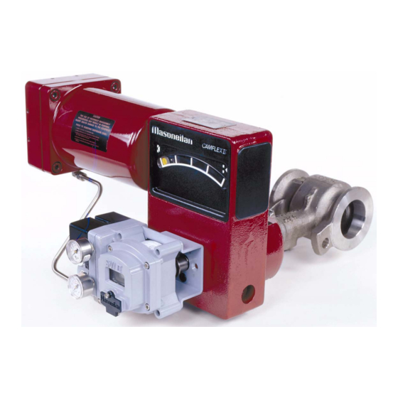
- Page 1 Masoneilan® Instruction N° Series 35002 EF 5000 E Camflex II Valve Instructions 01/2004 Includes rolling diaphragm, and manual actuator...
-
Page 2: Table Of Contents
Instruction No EF 5000 E 01/2004 Summary 1. - INTRODUCTION ........... 3 2. - GENERAL ............. 3 3. - PRINCIPLE OF OPERATION ....... 4 4. - UNPACKING ..........5 5. - INSTALLATION..........5 6. - AIR SUPPLY PIPING ........5 7. -
Page 3: Introduction
Instruction No EF 5000 E 01/2004 1. Introduction The following instructions are designed to assist the operation, maintenance and application of our maintenance personnel in performing most of the control valves and instruments. Arrangements for maintenance required on the Camflex® II valve and these services made... -
Page 4: Principle Of Operation
Instruction No EF 5000 E 01/2004 3. Principle of operation The concept of the Camflex® II valve is based on an The handwheel on Camflex® II is designed to be eccentrically rotating spherical plug contained in a used for emergency action only. free flow design ANSI Class 600 body. -
Page 5: Unpacking
Instruction No EF 5000 E 01/2004 E. If the valve is to be installed in a horizontal 4. Unpacking position, install the lower flange bolting to provide a cradle, which will help support, the valve while installing the remaining bolts. Care must be exercised when unpacking the valve to F. -
Page 6: Disassembly
Instruction No EF 5000 E 01/2004 that the valve be run through one cycle to insure orientation and the actuator to yoke orientation be proper functioning. Proceed as follows: marked in relation to each other. This will simplify reassembly. A. Back off the handwheel (53) so that it will not interfere with the operation of the valve and A. -
Page 7: Actuator Complete Disassembly
Instruction No EF 5000 E 01/2004 L. Loosen and remove cap screws (36) and A. In case of 35000 SB (Separable Bonnet) before lockwashers (37), then remove spring continuing in D it is necessary to loose and barrel (38). remove the nut 104 to separate the bonnet with the packing and the packing follower (15) from M. - Page 8 Instruction No EF 5000 E 01/2004 Note: The spacer tube (20) and upper guide wrenches be purchased or fabricated to facilitate bushing (21) may remain in the body. They removal and reassembly of the seat ring (2) since should be removed. The spacer tube (20) can SPECIFIC TORQUES MUST BE ACHIEVED to only be removed by pulling it out the bonnet end obtain tight shutoff and insure proper functioning of...
-
Page 9: Maintenance
Instruction No EF 5000 E 01/2004 Figure 6 shows the recommended thickness and 9. Maintenance method construction along with specific dimensions to facilitate construction. 9.1 SPRING DIAPHRAGM REPLACEMENT (Refer to figures 16 and 17) The recommended maintenance to be performed on the Camflex®... -
Page 10: Body S/A Internal Parts
Instruction No EF 5000 E 01/2004 Outer Face Glue Limit STEP A STEP B STEP C Figure 7 J. Roll the diaphragm (40) inside the spring barrel the sealing surface of the plug and seat ring. (38) until the bead on the diaphragm is located in the guide surface of the shaft and the guide the spring barrel groove (see figure 7, step B). -
Page 11: Yoke Assembly
Instruction No EF 5000 E 01/2004 E. Place seat ring on a flat surface with the seating F. Refer section actuator stem area facing up. adjustment. F. Apply a small amount of fine grinding compound 10.2 SPRING DIAPHRAGM ACTUATOR to the seat ring seating surface. ON BODY S/A G. -
Page 12: Handwheel Reassembly
Instruction No EF 5000 E 01/2004 Replace and tighten body stud nuts (27). place into the appropriate hole in the yoke and screw in clockwise. J. Replace packing flange stud nuts (94) and finger D. Replace the washer (51) and Truac ring (50) tighten only. -
Page 13: Seat Ring Alignment
Instruction No EF 5000 E 01/2004 D. Coat the upper guide bushing (21) spacer tube Q. Place the bonnet with the studs on the body and (20) and the shaft splines (plug side) with screw the nuts (104). recommended lubricant. R. -
Page 14: Dvd Plate Reassembly
Instruction No EF 5000 E 01/2004 G. Using the seat ring wrench, tighten seat ring 11. Actuator Stem Adjustment retainer to the minimum torque value specified in figure 12. Note: In some cases, for the valves from 3" to 12" (Refer to figures 16 and 17). - Page 15 Instruction No EF 5000 E 01/2004 position indicator mark on front cover (32). K. Gradually apply sufficient air pressure to extend clevis locknut (46) to an accessible position and tighten firmly. Caution: the relationship must be as shown in figure 18. If it is not, the yoke must be separated from the body and the lever (34) Caution: Do not exceed pressure listed in repositioned...
-
Page 16: Changing Body Position
Instruction No EF 5000 E 01/2004 Tighten clevis locknut (46). C. Remove bottom cover (11) (Snap fit.). D. Using a manual loading panel, apply sufficient air J. Relieve air pressure to actuator. pressure to the actuator to move the lever (34) to K. -
Page 17: Manual Actuator Option
Instruction No EF 5000 E 01/2004 now be installed, but insure it is backed off as not The disassembly procedure for manual actuator is to interfere with the operation of the lever at this similar to the procedure for spring diaphragm time. - Page 18 Instruction No EF 5000 E 01/2004 103 104 100 101 102 Figure 16 Figure 17...
- Page 19 Instruction No EF 5000 E 01/2004 PARTS REFERENCE Ref. Qty Part name Ref. Qty Part name Ref. Qty Part name BODY BODY STUD SERIAL PLATE SEAT RING REAR COVER PLATE SCREW RETAINER COVER SCREW BOSS COVER PLUG SCREW RETAINER COUNTER-FLANGE CLEVIS PIN CLIP FRONT COVER GASKET...
- Page 20 Instruction No EF 5000 E 01/2004 ACCEPTABLE NOT ACCEPTABLE Figure 18 AIR TO OPEN FLOW TENDING TO CLOSE CLOSE ON AIR FAILURE DIRECTION OF FLOW AIR TO CLOSE FLOW TENDING TO OPEN OPEN ON AIR FAILURE DIRECTION OF FLOW The body is shown behind the actuator. Figure 19 PACKING FLANGE REVERSED...
- Page 21 Instruction No EF 5000 E 01/2004 Figure 21...
- Page 22 Instruction No EF 5000 E 01/2004 Flanged bodies Long Stud (T) (64) Nuts Long Stud (T) (64) Nuts Long Stud (T) (64) Nuts Short Stud (G) (67) Short Stud (G) (67) Short Stud (G) (67) Valve Rating Length Length Length Dia.
- Page 23 Instruction No EF 5000 E 01/2004 Flangeless bodies Long Stud (T) (64) Long Stud (T) (64) Long Stud (T) (64) Short Blot (G) (67) Nuts Short Blot (G) (67) Nuts Short Bolt (G) (67) Nuts Cap screws (V) (65) Cap screws (V) (65) Cap screws (V) (65) Valve Rating Length...
- Page 24 DISTRIBUTOR E.P. & S. - FRANCE 24 bis rue de Picpus 75012 PARIS Tel: +33 (0)9 83 01 21 01 ventes@fr-eps.com E.P. & S. - CAMEROON Immeuble Carré d'Or, Rue Njo-Njo Bonapriso, DOUALA Tel: +237 6 52 12 70 95 ventes@fr-eps.com Visit your web-site: www.fr-eps.com...
Need help?
Do you have a question about the Masoneilan Camflex II 35002 Series and is the answer not in the manual?
Questions and answers